Floor drain cover plate of anti-blocking easy drainage roof

A floor drain cover and anti-blocking technology, applied in the direction of roof drainage, roof covering, roof, etc., can solve the problem of easy blockage of drainage efficiency, and achieve the effect of avoiding a large amount of accumulation and high drainage efficiency.

Inactive Publication Date: 2020-08-14
杨照联
View PDF8 Cites 2 Cited by
  • Summary
  • Abstract
  • Description
  • Claims
  • Application Information

AI Technical Summary

Problems solved by technology

[0005] The object of the present invention is to provide an anti-clogging and easy-drainage roof floor drain cover with high drainage efficiency and no easy clogging for the above-mentioned problems of drainage efficiency and easy clogging

Method used


Image

  • Floor drain cover plate of anti-blocking easy drainage roof
  • Floor drain cover plate of anti-blocking easy drainage roof
  • Floor drain cover plate of anti-blocking easy drainage roof

Examples


Embodiment 1

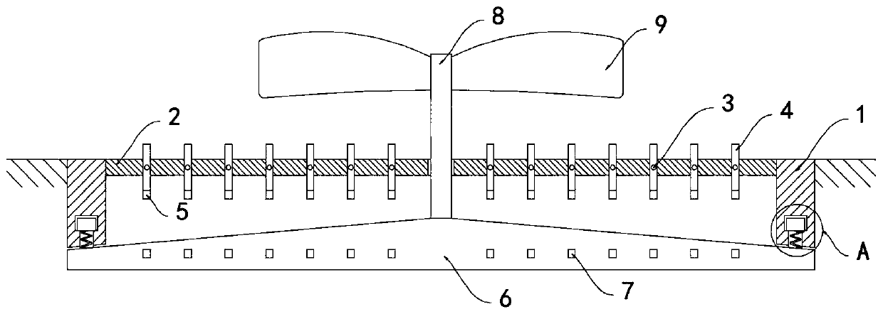
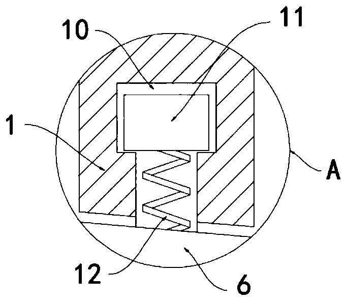
[0021] like Figure 1-4 As shown, an anti-blocking and easy-to-drain roof floor drain cover plate includes an annular shell 1, and the upper end of the annular shell 1 is fixedly equipped with a plurality of equidistant and horizontally arranged ribs 2, and a support shaft 3 vertically runs through the ribs 2. , both ends of the support shaft 3 are equipped with a water-repellent sheet 4, the water-repellent sheet 4 can freely rotate around the support shaft 3, the lower end of the water-repellent sheet 4 is fixedly connected with a magnetic counterweight 5, and the lower end of the annular shell 1 is pulled The stretching mechanism is equipped with a sealing plate 6, and the stretching mechanism includes an annular limiting groove 10 arranged at the bottom of the annular housing 1. Two limiting blocks 11 are rotationally connected in the annular limiting groove 10, and the lower end of the limiting block 11 is reset. The spring 12 is fixed with the sealing plate 6, and the se...

Embodiment 2

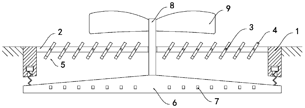
[0026] like Figure 5 As shown, the difference between this embodiment and Embodiment 1 is that: the upper surface of the sealing plate 6 is provided with a plurality of water distribution strips 13 extending from the center to the surroundings, and the plurality of water distribution strips 13 are arranged in an annular array.

[0027] In this embodiment, when the sealing plate 6 rotates, it drives the water divider 13 to rotate, and the water divider 13 can push the rainwater on the surface of the seal plate 6 to rotate quickly, preventing the rainwater from sliding and flowing along the tangential direction on the surface of the seal plate 6, thereby enhancing The centrifugal effect on rainwater further improves its drainage efficiency.


PUM


Abstract

The invention belongs to the field of sponge city construction, in particular to a floor drain cover plate of an anti-blocking easy drainage roof. The floor drain cover plate comprises an annular housing, wherein a plurality of horizontally arranged fillets in an equally spaced manner are fixedly mounted at the upper end of the annular housing, a supporting shaft penetrates the fillets vertically,water stirring pieces are mounted at two ends of the supporting shaft, the water stirring pieces can rotate around the supporting shaft freely, magnetic counterweights are fixedly connected to the lower ends of the water stirring pieces, a sealing plate is mounted at the lower end of the annular housing through a stretching mechanism, the sealing plate protrudes upward from four sides to center,a plurality of permanent magnets are embedded into the sealing plate, the permanent magnets are aligned to the magnetic counterweights and the heteropoles attract each other, a rotating shaft is fixedly mounted at the upper end of the sealing plate, and the upper end of the rotating shaft stretches to the upper side of the fillets and is fixedly connected to a wind wheel. According to the floor drain cover plate, the position of the sealing plate is adjusted according to rainfall or not, so that the floor drain cover plate of the roof is further controlled to open and close. The floor drain cover plate has two advantages of efficient draining and anti-blocking.

Description

technical field [0001] The invention belongs to the field of sponge city construction, and in particular relates to an anti-blocking and easy-drainage roof floor drain cover plate. Background technique [0002] In the construction of sponge cities, the roofs of residential buildings, buildings and other high-rise buildings need to be equipped with floor drains to remove the top drainage, so as to prevent the impact of water on the roofs on the residents during rainy weather. With the deterioration of the environment, the city's Dust and debris are often carried in the air, which fall from the roof floor drain into the drain pipe, causing blockage. [0003] There are two types of existing floor drains on the roof. One is composed of multiple ribs. This kind of floor drain has a better drainage effect, but it cannot prevent debris from falling into the drain pipe, which will easily cause the problem of blockage of the drain pipe over time. The first is a sealing cover with dr...

Claims


Application Information

Patent Timeline
Patent Type & Authority Applications(China)
IPC IPC(8): E04D13/04
CPCE04D13/0409E04D2013/0427
Inventor 杨照联陈超胜
Owner 杨照联
Why Eureka
Try Eureka