Complex formed multi-tooth tool and machining method and application method thereof

One tool, complex technology

Pending Publication Date: 2020-08-18
CHENGDU TOOL RES INST
View PDF10 Cites 0 Cited by
  • Summary
  • Abstract
  • Description
  • Claims
  • Application Information

AI Technical Summary

Problems solved by technology

[0006] The present invention intends to provide a multi-tooth tool with complex shape to solve the problems of unstable machining process and low cutting precision of existing multi-tooth tools

Method used


Image

  • Complex formed multi-tooth tool and machining method and application method thereof
  • Complex formed multi-tooth tool and machining method and application method thereof
  • Complex formed multi-tooth tool and machining method and application method thereof

Examples


Embodiment 1

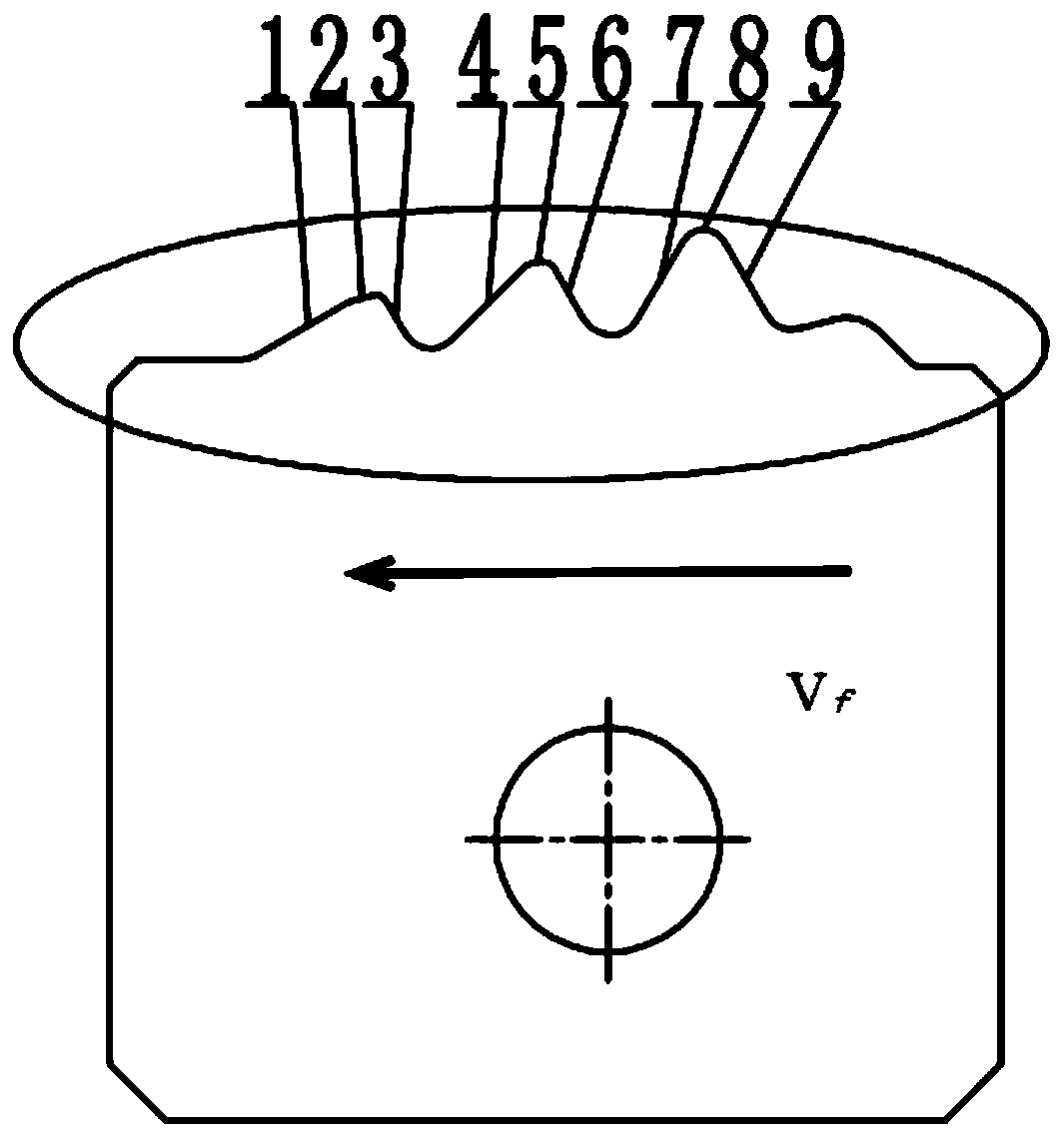
[0048] The embodiment is basically as attached figure 1 As shown: the multi-tooth tool with complex forming in this embodiment is a new structure of the cutting tool with the combination of rough cutting teeth and the optimal cutting angle combined inclined top layered peeling cutting principle, which realizes efficient and stable machining of rough cutting teeth and satisfies precision requirements. Precision machining requirements for cutting teeth. The complex shaped multi-tooth cutter in this embodiment has at least two rough cutting teeth and one fine cutting tooth. The rough cutting tooth means the rough cutting tooth, and the fine cutting tooth means the fine cutting tooth. Such as figure 1 As shown, from left to right there are the first rough cutting tooth, the second rough cutting tooth and the fine cutting tooth, and the cutting process is carried out along the feed direction of Vf. The role of fine cutting teeth is the final forming process to form the complex sh...

Embodiment 2

[0060] The difference from Embodiment 1 is that in this embodiment, there are three rough incisors and one fine incisor, and the heights of all incisors gradually increase along the feed direction, wherein the height of the latter incisor is 1.1- 1.5 times. This setting is beneficial to make the previous cutting tooth not only effectively remove and peel off the workpiece to be processed, but also provide a gentle transition for the contact between the workpiece to be processed and the next cutting tooth, so that the force on the entire multi-tooth tool is balanced, and avoid the force caused by uneven force. various problems.

Embodiment 3

[0062] The difference from the first embodiment is that the complicated multi-tooth cutter in this embodiment is made of cemented carbide.


PUM


Abstract

The invention relates to the technical field of special turning, in particular to a complex formed multi-tooth tool. The complex formed multi-tooth tool comprises at least two rough cutting teeth andat least one finish cutting tooth successively arranged in a feeding direction. The rough cutting teeth and the finish cutting teeth form a comb-like structure together. Each rough cutting tooth comprises a first cut-in surface of the rough cutting tooth, a top line of the rough cutting tooth and a later cut-in surface of the rough cutting tooth. Each finish cutting tooth comprises a first cut-insurface of the finish cutting tooth, a top line of the finish cutting tooth and a later cut-in surface of the finish cutting tooth. The later cut-in surface of the rough cutting tooth and the later cut-in surface of the finish cutting tooth are homodromous. The included angles between the first cut-in surfaces of all the rough cutting teeth and a vertical direction are larger than those between the first cut-in surfaces of all the finish cutting teeth and the vertical direction. The invention further relates to a machining method and an application method of the complex formed multi-tooth tool. According to the invention, a vibrating problem in a tool using process can be reduced effectively, so that the tool is stressed in a balanced manner, and therefore, the service life of the tool isprolonged and the machining precision is improved.

Description

technical field [0001] The invention relates to the technical field of special turning, in particular to a multi-tooth cutting tool with complex shape and its processing method and usage method. Background technique [0002] Turning is a commonly used mechanical processing method. For most products, general-purpose parts can be directly used for turning and cutting. However, when processing some workpieces with special requirements, special parts must be replaced. [0003] In the field of special turning technology, complex forming processing occupies a large proportion. Complex forming processing usually requires a large machining allowance for cutting and peeling. In order to improve efficiency and the quality of the processed surface, complex forming comb tools are usually used for simultaneous processing. . [0004] Existing multi-tooth tools for complex forming generally include rough cutting and fine cutting. The rough cutting of the tool first cuts off most of the ma...

Claims


Application Information

Patent Timeline
IPC IPC(8): B23B27/06B23P15/30
CPCB23B27/06B23P15/30
Inventor 陈云刘洪李代刚曾莉耿子瑜
Owner CHENGDU TOOL RES INST
Why Eureka
Try Eureka