Supercharge Your Innovation With Domain-Expert AI Agents!

Electric connector jack, electric connector female end and electric connector

A technology of electrical connectors and female terminals, which is applied in the direction of connection and connection device components, circuits, etc., can solve the problems of socket falling off and insertion force reduction, and achieve large insertion force, good resilience performance, and connection good effect

Pending Publication Date: 2020-08-18
天津君磊科技有限公司
View PDF0 Cites 0 Cited by
  • Summary
  • Abstract
  • Description
  • Claims
  • Application Information

AI Technical Summary

Problems solved by technology

[0002] Electrical connectors generally include a male end and a female end. One end of the male end is connected to an electrical appliance or wire, and the other end is provided with a pin. One end of the female end is connected to an electrical appliance or wire, and the other end is provided with a jack, and the pin is inserted into the jack The electrical appliances and / or wires are connected as a whole, and the pins and sockets are all arranged in an insulating shell. At present, the outer side of the female end of most electrical connectors is relatively smooth and does not have too many structures. Therefore, when using this In the case of electrical connectors, the female end of the electrical connector is prone to the phenomenon that the jack will fall off from the shell when it is heated. Moreover, when the existing electrical connector is used more times, the insertion and withdrawal force of the jack to the pin will become smaller. Therefore, Need a kind of novel electric connector badly to solve the above-mentioned situation

Method used


Image

  • Electric connector jack, electric connector female end and electric connector

Examples


Embodiment 1

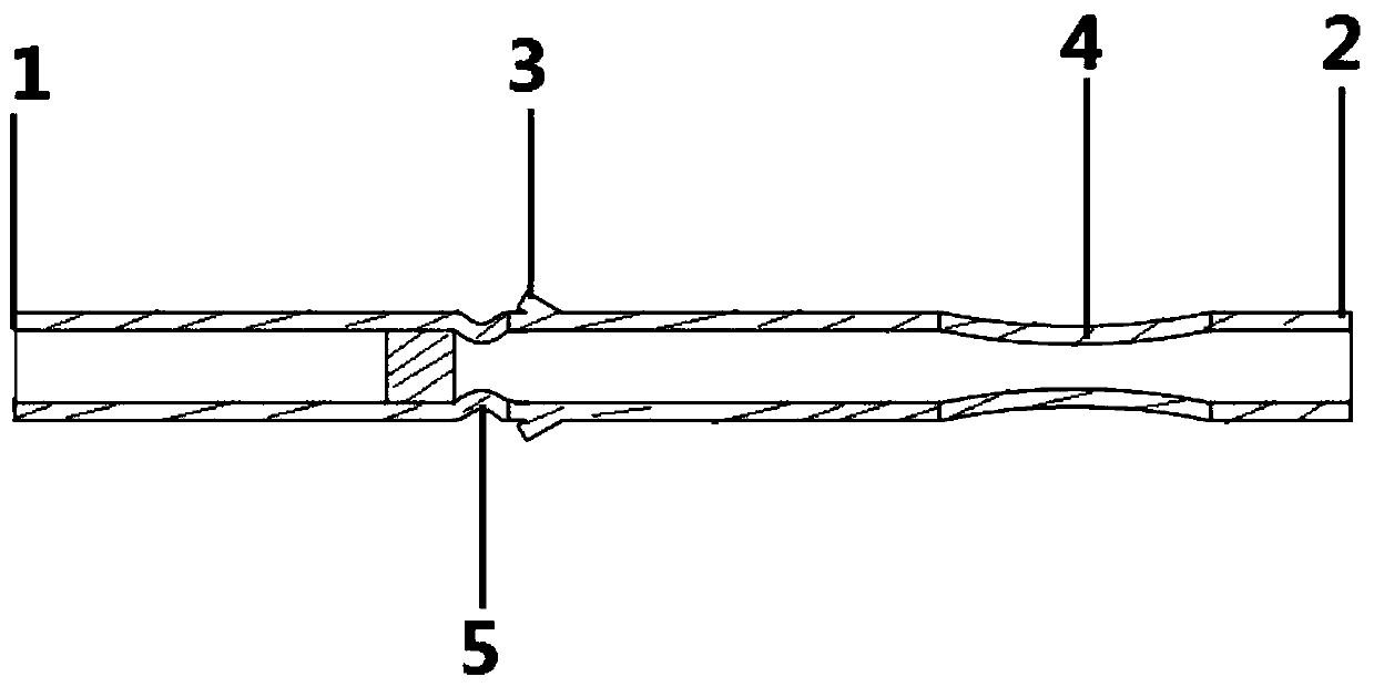
[0021] This embodiment provides an electrical connector jack, such as figure 1 As shown, it includes: the jack body, the jack body is tubular, the jack body is metal, and can conduct electricity, the two ends of the jack body are the first end 1 and the second end 2, and the first end 1 is used for fixed connection The wire, the second end 2 is used to insert the contact pin, the middle part of the jack body is provided with an annular inner groove 5, the jack body between the annular inner groove 5 and the second end 2 is used to be arranged in the insulating shell, the annular The socket body between the inner groove 5 and the first end 1 protrudes from the insulating shell, and the wall of the socket body near the second end 2 is concave, forming a locking needle part 4, and the annular inner groove 5 A hook body 3 is provided on the pipe wall of the part of the socket body between the lock needle part 4 to form an anti-off part. One end of the hook body 3 is connected to t...

Embodiment 2

[0027] This embodiment provides a female end of an electrical connector, including an insulating shell and the electrical connector socket in Embodiment 1. The insulating shell is a sleeve with two ends open, and the insulating shell is sheathed and fixed on the outer tube of the socket body. On the wall, the first end 1 protrudes from the insulating shell, the second end 2 does not protrude from the insulating shell, and the pin is inserted into the socket body from the second end 2 .

Embodiment 3

[0029] This embodiment provides an electrical connector, including: the male end of the electrical connector and the female end of the electrical connector in Embodiment 2, the male end of the electrical connector is provided with a pin, and the pin is inserted into the socket from the second end 2 in the ontology.


PUM


Abstract

The invention discloses an electric connector jack. The invention relates to the technical field of connector structures, and the jack comprises a jack body, wherein two ends of the jack body are respectively a first end and a second end. An annular inner groove is formed in the middle of the jack body; the jack body between the annular inner groove and the first end extends out of the insulatingshell; the pipe wall of the part, close to the second end, of the jack body is concave inwards to form a lock pin part, a hook body is arranged on the pipe wall of the part, between the annular innergroove and the lock pin part, of the jack body to form an anti-disengagement part, one end of the hook body is connected to the pipe wall, and the other end of the hook body extends in the direction away from the pipe wall; a plurality of long holes are uniformly formed in the circumferential direction of the tube wall of the needle locking part, the tube wall of the needle locking part is arc-shaped, and the inner diameter of the needle locking part is gradually reduced from two ends to the middle; the invention also discloses an electric connector and an electric connector female end. According to the technical scheme provided by the invention, the jack is not easy to fall off, and the plugging force of the jack to the contact pin is still relatively large after the jack is used for manytimes.

Description

technical field [0001] The invention relates to the technical field of connector structures, in particular to an electrical connector socket, an electrical connector female end and an electrical connector. Background technique [0002] Electrical connectors generally include a male end and a female end. One end of the male end is connected to an electrical appliance or wire, and the other end is provided with a pin. One end of the female end is connected to an electrical appliance or wire, and the other end is provided with a jack, and the pin is inserted into the jack The electrical appliances and / or wires are connected as a whole, and the pins and jacks are all arranged in an insulating shell. At present, the outer side of the jack of most electrical connectors is relatively smooth and does not have too many structures, so it leads to the use of this In the case of electrical connectors, the female end of the electrical connector is prone to the phenomenon that the socket ...

Claims


Application Information

Patent Timeline
IPC IPC(8): H01R13/20H01R13/11H01R13/405
CPCH01R13/11H01R13/20H01R13/405
Inventor 姜涛
Owner 天津君磊科技有限公司
Features
  • R&D
  • Intellectual Property
  • Life Sciences
  • Materials
  • Tech Scout
  • Unparalleled Data Quality
  • Higher Quality Content
  • 60% Fewer Hallucinations
Learn More