
Eureka
For R&D, Eureka makes reading and utilizing patents & technical documents easy.
Eureka AIR
Designed for self-driven R&D workflows. Generate viable solutions, solve complex R&D challenges, empower your innovation with AI.

Eureka Materials
Designed for material experts only. Revolutionize your material R&D, from search, analyze, to developing new materials.

TechResearch
Generate reliable direction feasibility study reports for your R&D in just a few steps.

TechSeek
Discover and master advanced knowledge NOW. Basics, ideas, possibilities, all at once.

TechMind
As an expert in R&D Theories, TechMind can generates customized viable solutions instantly.

TechRisk
Analyze your overall solution with one click, know your potential R&D risks in advance.

TechMonitor
Get weekly tech updates, stay abreast of the latest tech innovations and key insights.
Novel snap spring anti-loosening connector
An anti-loosening and connector technology, applied in the direction of connection, parts and electrical components of the connection device, etc., can solve the problems of low reliability, inconvenient installation and complex structure.
- Summary
- Abstract
- Description
- Claims
- Application Information
AI Technical Summary
Problems solved by technology
Method used
Image

Examples
Embodiment Construction
[0036] In order to further explain the technical means and effects of the present invention to achieve the intended purpose of the invention, the specific implementation methods, Structure, characteristic and effect thereof are as follows in detail.
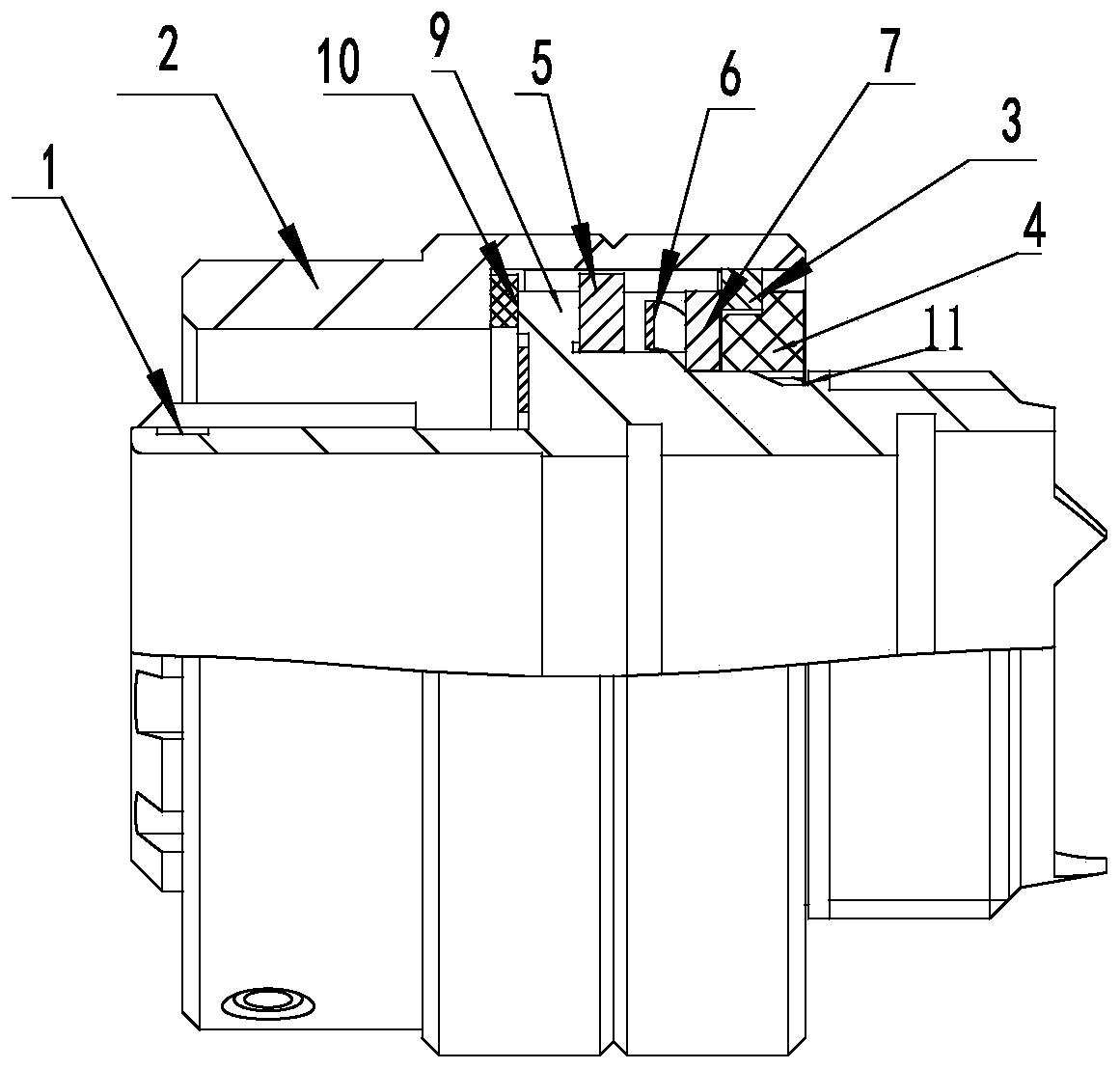
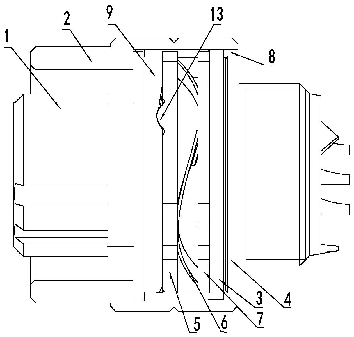
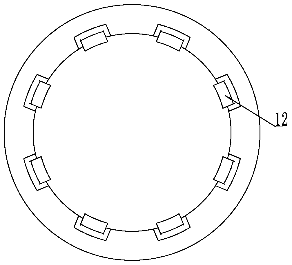
[0037] see Figure 1-6 , which is a structural schematic diagram of a new spring anti-loosening connector of the present invention. The connector includes an outer shell 1 and a connecting nut 2 that is rotatably assembled outside the outer shell. The front end of the collar 4 on the outer casing 1 and axially limited by the outer casing 1 extends into the inner ring of the jumper 3 to prevent the jumper from shrinking inwardly and disengaging from the connecting nut.
[0038] An anti-loosening component is also provided between the outer shell and the connecting nut, and the anti-loosening component is axially limited by the snap spring 3 . Preferably, the outer periphery of the front end of the collar 4 is in contact with the...
PUM
 Abstract
Description
Claims
Application Information
 - R&D Engineer
- R&D Manager
- IP Professional
- Industry Leading Data Capabilities
- Powerful AI technology
- Patent DNA Extraction
Browse by: Latest US Patents, China's latest patents, Technical Efficacy Thesaurus, Application Domain, Technology Topic, Popular Technical Reports.
© 2024 PatSnap. All rights reserved.Legal|Privacy policy|Modern Slavery Act Transparency Statement|Sitemap|About US| Contact US: help@patsnap.com