Self-adaptive wind barrier system

An adaptive, wind barrier technology, applied to bridge parts, bridges, buildings, etc., can solve problems such as bridge deck shaking and potential safety hazards, and achieve the effects of avoiding bending, improving safety factor, and strengthening connection relationship

Inactive Publication Date: 2020-08-21
常金法
View PDF0 Cites 0 Cited by
  • Summary
  • Abstract
  • Description
  • Claims
  • Application Information

AI Technical Summary

Problems solved by technology

[0002] For the development and construction of highways, intercity railways, urban expressways, and bridges, when they are built in strong wind areas, the bridge pavement under the action of cross winds will have similar wind speeds above and below the bridge deck, forming common frequency vibrations, which will cause the bridge deck to shake , there are potential safety hazards, so an adaptive wind barrier system is needed to adjust and change the wind speed on the bridge deck to improve the safety factor of the bridge

Method used


Image

  • Self-adaptive wind barrier system
  • Self-adaptive wind barrier system
  • Self-adaptive wind barrier system

Examples


Embodiment 1

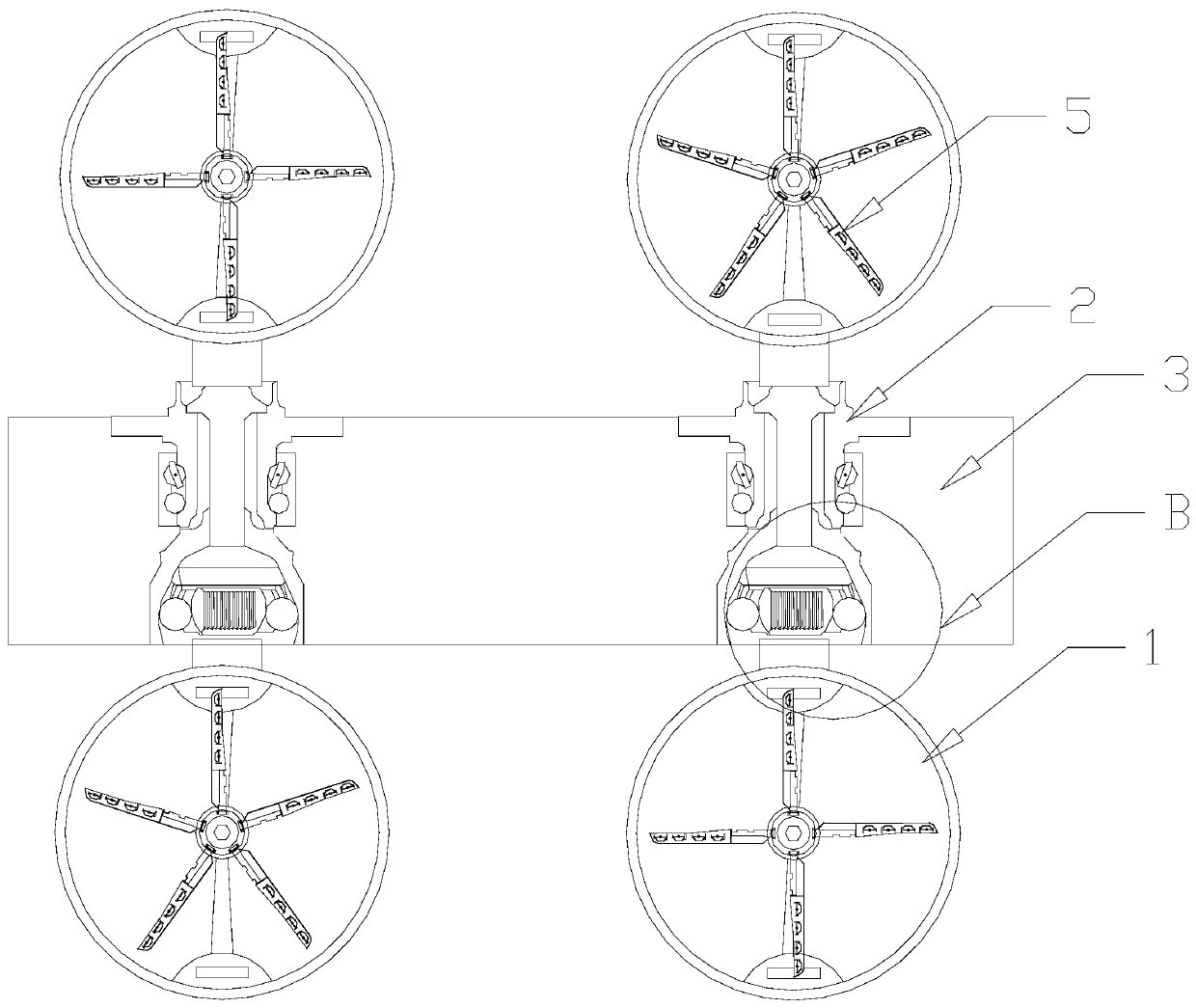
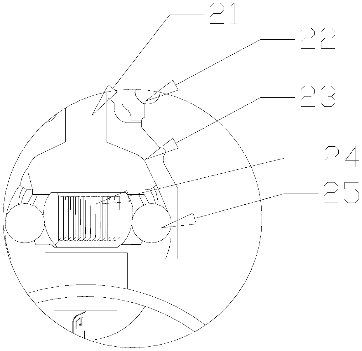
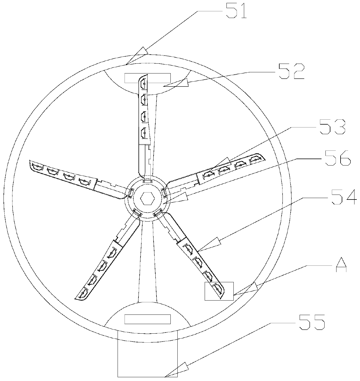
[0024] see Figure 1-Figure 5 , an adaptive wind barrier system, the present invention provides an adaptive wind barrier system, its structure includes a first wind barrier and a second wind barrier, the second wind barrier includes a first wind barrier row 1, Connecting pile 2, bridge deck 3, and second wind barrier row 5, the connecting pile 2 is installed in the middle of the side of the bridge deck 3, and the upper and lower ends of the connecting pile 2 are respectively provided with a first wind barrier row 1 and a second wind barrier row Row 5, the first wind barrier row 1 and the second wind barrier row 5 are mechanically connected to the connecting pile 2, the horizontal first wind barrier row 1 or the horizontal first wind barrier row 1 or the horizontal first wind barrier row 1 of the adjacent first wind barrier and the second wind barrier The difference in the number of blades 54 in the two wind barrier rows 5 is one, which ensures that the wind speeds within a sho...

Embodiment 2

[0030] see Figure 1-Figure 5 , an adaptive wind barrier system, the present invention provides an adaptive wind barrier system, its structure includes a first wind barrier and a second wind barrier, the second wind barrier includes a first wind barrier row 1, Connecting pile 2, bridge deck 3, and second wind barrier row 5, the connecting pile 2 is installed in the middle of the side of the bridge deck 3, and the upper and lower ends of the connecting pile 2 are respectively provided with a first wind barrier row 1 and a second wind barrier row Row 5, the first wind barrier row 1 and the second wind barrier row 5 are mechanically connected to the connecting pile 2, the horizontal first wind barrier row 1 or the horizontal first wind barrier row 1 or the horizontal first wind barrier row 1 of the adjacent first wind barrier and the second wind barrier The difference in the number of blades 54 in the two wind barrier rows 5 is one, which ensures that the wind speeds within a sho...


PUM


Abstract

The invention discloses a self-adaptive wind barrier system structurally comprising a first wind barrier device and a second wind barrier device. The second wind barrier device comprises a first windbarrier row, connecting piles, a bridge floor and a second wind barrier row; the connecting piles are arranged between side surfaces of the deck; and the first wind barrier row and the second wind barrier row are respectively arranged at upper and lower ends of the connecting piles. The difference between the numbers of blades in the first horizontal wind barrier row and the second horizontal windbarrier row of the first wind barrier device and the second wind barrier device which are adjacent is one. By rotating the crescent moon structure, whether the semi-crescent moon plate faces the wind direction directly or not is adjusted and thus the local wind speed is changed, so that the wind speed difference between every two adjacent wind barrier rows is increased or decreased, the two adjacent wind barrier rows are inconsistent in speed, and the problems are solved.

Description

technical field [0001] The invention relates to the field of road equipment, in particular to an adaptive wind barrier system. Background technique [0002] For the development and construction of highways, intercity railways, urban expressways, and bridges, when they are built in strong wind areas, the bridge pavement under the action of cross winds will have similar wind speeds above and below the bridge deck, forming common frequency vibrations, which will cause the bridge deck to shake , there are potential safety hazards, so an adaptive wind barrier system is needed to adjust and change the wind speed above and below the bridge deck to improve the safety factor of the bridge. Contents of the invention [0003] Aiming at the deficiencies of the prior art, the present invention is realized through the following technical solutions: an adaptive wind barrier system, the structure of which includes a first wind barrier and a second wind barrier, and the second wind barrier...

Claims


Application Information

Patent Timeline
IPC IPC(8): E01D19/00
CPCE01D19/00
Inventor 常金法
Owner 常金法
Why Eureka
Try Eureka