Filter device

A filter and equipment technology, applied in the field of filter equipment, can solve the problems of process safety and equipment availability still to be improved, and achieve the effect of reducing mechanical load

Active Publication Date: 2020-08-21
HYDAC PROCESS TECH
View PDF10 Cites 0 Cited by
  • Summary
  • Abstract
  • Description
  • Claims
  • Application Information

AI Technical Summary

Problems solved by technology

As a result, process safety and plant availability have yet to be improved in known filter plants

Method used


Image

  • Filter device
  • Filter device
  • Filter device

Examples


Embodiment Construction

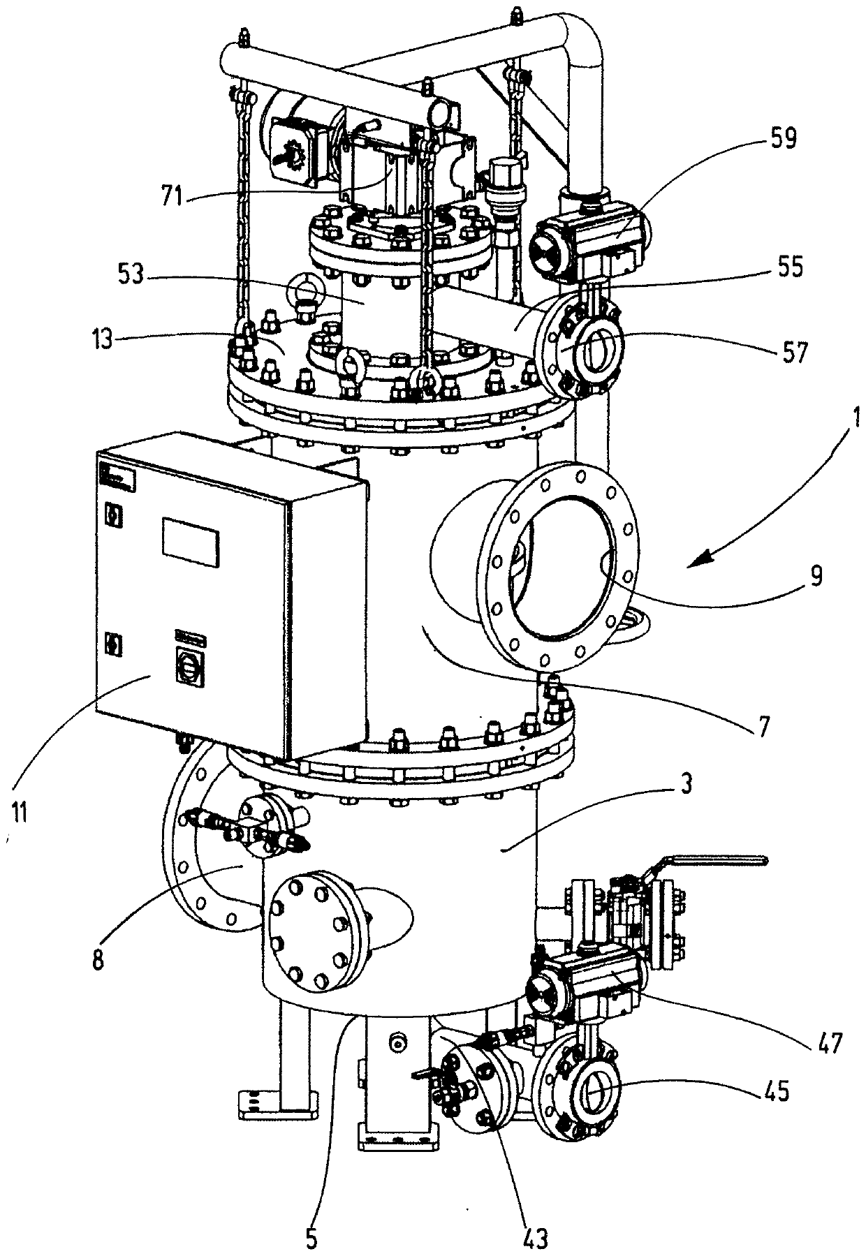
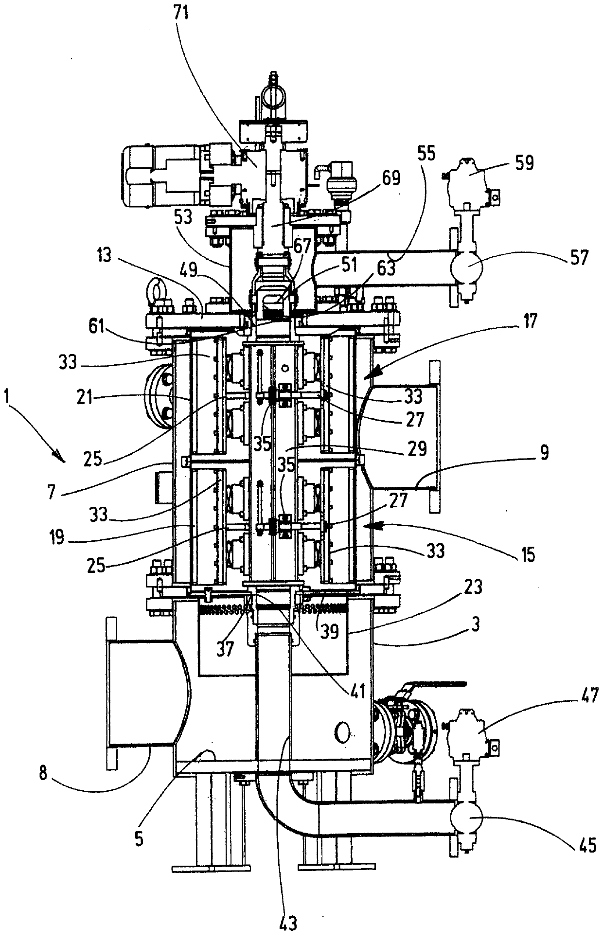
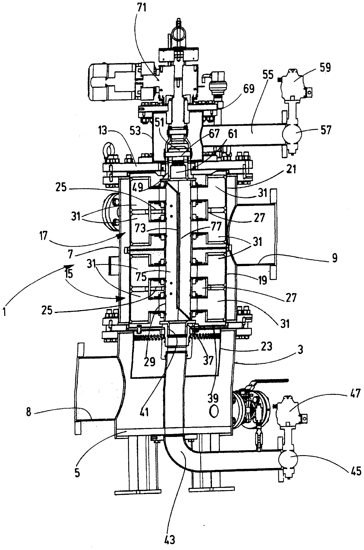
[0024] In the embodiment of the filter device according to the invention shown as a whole Figure 1 to Figure 4 In , the filter housing as a whole is marked with 1. The two-part filter housing 1 has a cylindrical inlet part 3 with a closed bottom 5 . Arranged on the input part 3 is a housing body part 7 which, like the input part 3 , is cylindrical. On the side wall of the inlet part 3 there is a fluid inlet 8 for flowing unfiltered liquid into said inlet part and a fluid outlet 9 for filtrate is located on the side wall of the body part 7 . like figure 1 As shown, on the outside of the body part 7 a switch box 11 is mounted, said switch box essentially containing an electronic filter control according to the prior art. The body part 7 is closed at the top by a cover part 13 . Received in the main part 7 are a lower filter core 15 and an upper filter core 17 whose filter screens 19 or 21 are pierced from the inside to the outside during the filtration process. flow. Unfi...


PUM


Abstract

The invention relates to a filter device comprising a filter housing (1) having a fluid inlet (8) for non-filtrate and having a fluid outlet (9) for filtrate, and comprising at least one single- or multi-part filter cartridge (15, 17) accommodated in the filter housing (1), which cartridge can be cleaned using a backwash device (25) having at least one backwash organ (31) in countercurrent to thefilter direction, which backwash device can be moved along the inner face of the filter cartridge (15, 17) in question by means of a fluid-conducting driveshaft (29) of a rotary drive (69, 71), wherein each backwash organ (31) has at least one gap-like through-opening on its end adjacent to said inner face, said through-opening extending parallel to the rotational axis of the drive shaft (29) andleading into a flow chamber fluidically connected to the drive shaft (29). The filter device is characterised in that at least one additional backwash device (27) having at least one additional backwash organ (31) is provided, the fluid-conducting drive shaft (29) is divided into chambers (73, 75) which are separated from one another, and one backwash organ (31) of one backwash device (25) is connected to one of the chambers (73, 75), and the other backwash organ (31) of the other backwash device (27) is connected to the other chamber (73, 75).

Description

technical field [0001] The invention relates to a filter device having a filter housing with a fluid inlet for unfiltered liquid and with a fluid outlet for filtrate and at least one filter housed in the filter housing. One-piece or multi-piece filter inserts which can be cleaned in countercurrent to the filtration direction by means of a backflushing device having at least one backflushing mechanism by means of a rotary drive The fluid-guiding drive shaft is movable along the inner side of the corresponding filter core, wherein the corresponding backwash mechanism has at least one gap-shaped through opening on its end adjacent to the inner side, the through opening It extends parallel to the axis of rotation of the drive shaft, and the through-opening opens into a flow chamber that is connected fluidically to the drive shaft. Background technique [0002] Such filter devices are prior art, see eg DE 20 2011 000 268U. The possibility to clean the filter insert by backwashi...

Claims


Application Information

Patent Timeline
Patent Type & Authority Applications(China)
IPC IPC(8): B01D29/11B01D29/54B01D29/68
CPCB01D29/117B01D29/54B01D29/682B01D29/688B01D2201/082B01D29/52B01D29/668
Inventor B·施里希特J·H·格斯特纳A·凯因特斯
Owner HYDAC PROCESS TECH
Why Eureka
Try Eureka