
Punching device capable of automatically cooling outer wall of punching cavity

A stamping device, automatic technology, applied in the field of stamping

Inactive Publication Date: 2020-08-25
朱健斌
View PDF7 Cites 0 Cited by
  • Summary
  • Abstract
  • Description
  • Claims
  • Application Information

AI Technical Summary

Problems solved by technology

[0005] Aiming at the deficiencies of the prior art, the present invention provides a stamping device that can automatically cool down the outer wall of the stamping cavity, which has the advantages of automatically cooling the outer wall of the stamping without stopping the stamping operation, and solves the need to stop working every time during the stamping process. The problem of applying coolant to the stamping cavity

Method used


Image

  • Punching device capable of automatically cooling outer wall of punching cavity
  • Punching device capable of automatically cooling outer wall of punching cavity
  • Punching device capable of automatically cooling outer wall of punching cavity

Examples


Embodiment Construction

[0024] The technical solutions in the embodiments of the present invention will be clearly and completely described below in conjunction with the accompanying drawings in the embodiments of the present invention. Obviously, the described embodiments are only a part of the embodiments of the present invention, rather than all the embodiments. Based on the embodiments of the present invention, all other embodiments obtained by those of ordinary skill in the art without creative work shall fall within the protection scope of the present invention.

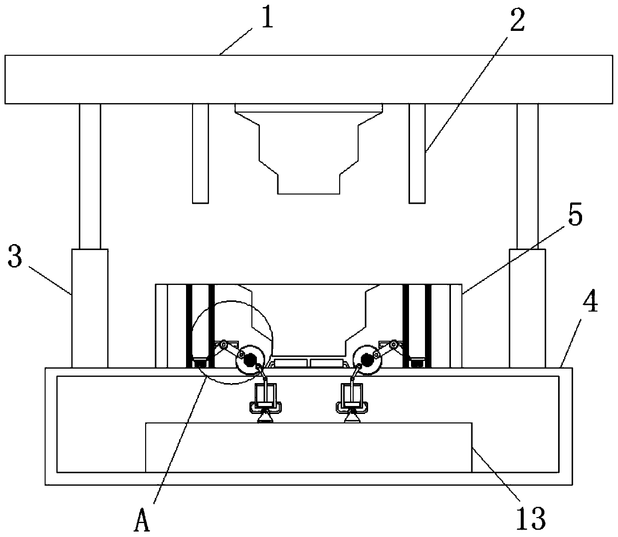
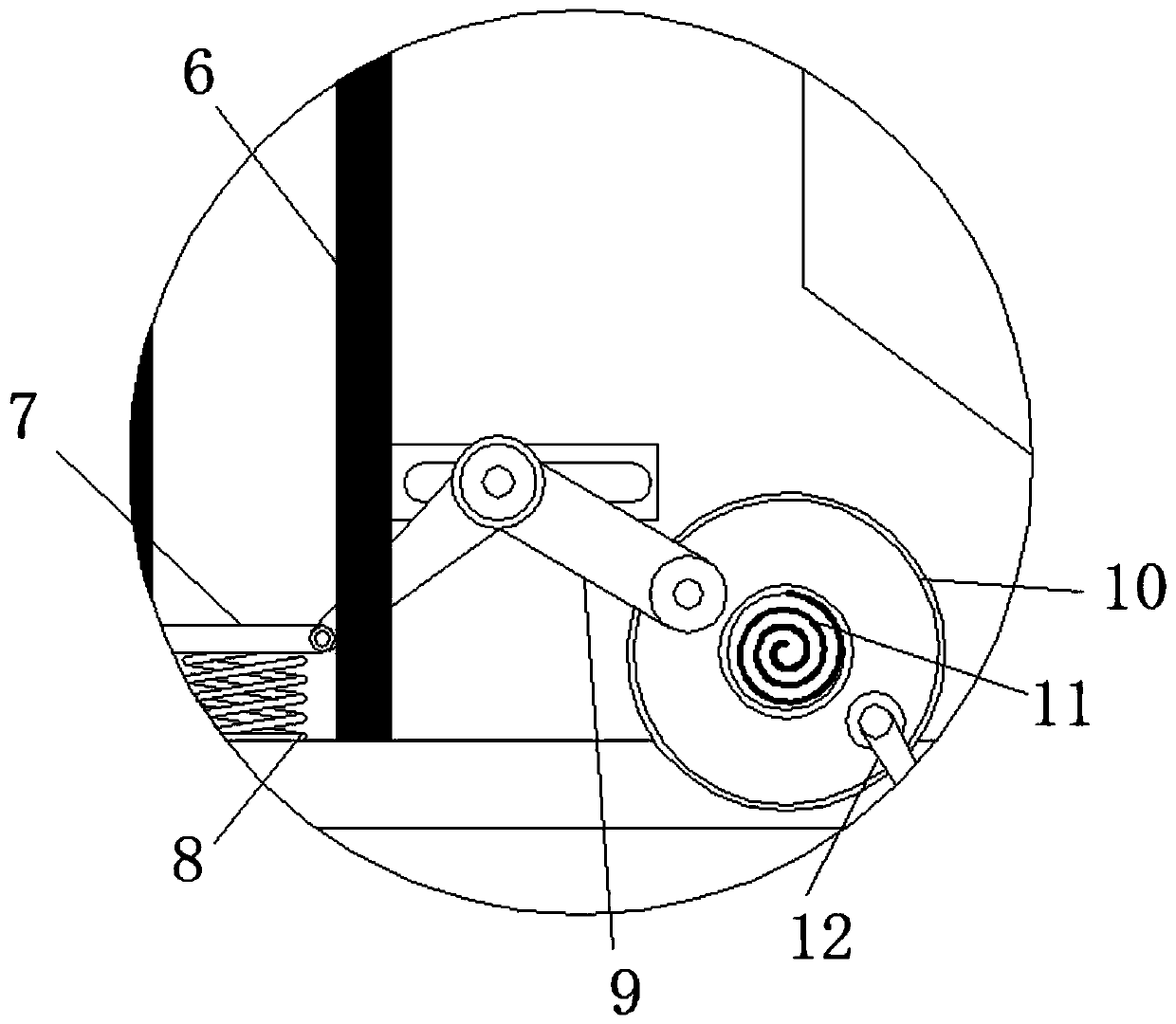
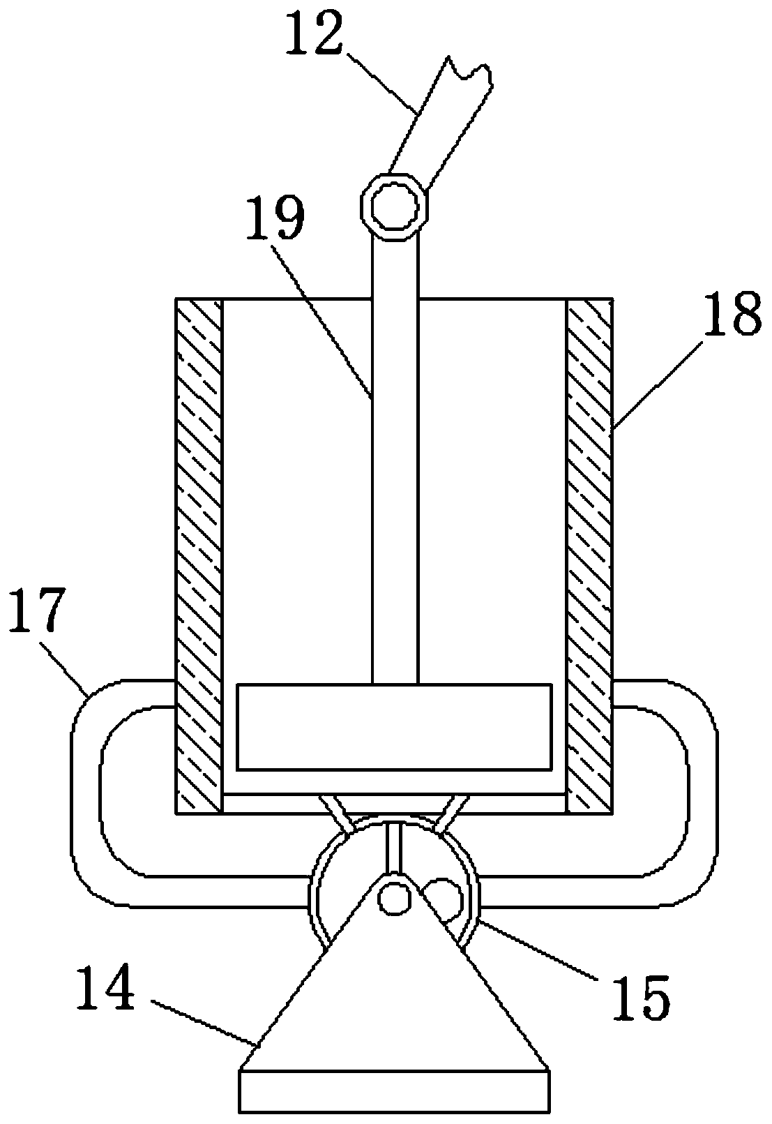
[0025] See Figure 1-5 , A stamping device that can automatically cool the outer wall of the stamping cavity, including an upper template 1. The left and right ends of the bottom of the upper template 1 are fixedly installed with guide rods 2, and the left and right ends of the bottom of the upper template 1 are fixedly connected by a lifting device 3. There is a lower template 4, the upper end of the lower template 4 is fixedly installe...


PUM


Abstract

The invention relates to the technical field of punching, and discloses a punching device capable of automatically cooling the outer wall of a punching cavity. The punching device comprises an upper template. Guide rods are fixedly mounted at the left end and the right end of the bottom of the upper template. The left end and the right end of the bottom of the upper template are fixedly connectedwith a lower template through lifting devices. A punching block is fixedly mounted at the upper end of the lower template. Guide rail groove bodies are fixedly mounted at the left end and the right end of the punching block. Moving plates are movably mounted at the lower ends of the guide rail groove bodies, and first springs are fixedly mounted at the lower ends of the moving plates. According tothe punching device capable of automatically cooling the outer wall of the punching cavity, the guide rods enter the guide rail groove bodies downwards to drive the moving plates to move, the movingplates drive V-shaped connecting rods to move, piston rods are driven by cooperating with the action of rotating wheels to move in piston barrels, and therefore condensation liquid can be automatically drawn from a liquid storage groove body to enter a condensation liquid pipe, and the effect of cooling the punching cavity is achieved.

Description

Technical field [0001] The invention relates to the technical field of stamping, in particular to a stamping device that can automatically cool the outer wall of a stamping cavity. Background technique [0002] Stamping relies on presses and dies to apply external force to plates, strips, pipes and profiles to cause plastic deformation or separation, thereby obtaining workpieces (stamping parts) of the required shape and size. Many motor housings rely on stamping The motor shell formed by the process has high precision and consistent specifications, and it is not easy to be thermally deformed during use. [0003] During stamping overshoot, it is easy to cause heat to be generated on the inner wall of the mold cavity. If the heat is not dissipated in time, it may cause the mold to be heated and deform during the stamping process, resulting in the stamping parts produced not meeting specifications. The current heat dissipation method is Applying the extremely volatile "quick-drying ...

Claims


Application Information

Patent Timeline
Patent Type & Authority Applications(China)
IPC IPC(8): B21D37/16B21D22/02
CPCB21D22/02B21D37/16
Inventor 朱健斌
Owner 朱健斌
Learn More