
Universal type crankshaft fixture

A general-purpose, crankshaft technology, applied in the field of crankcases, can solve problems such as complex structure, numerous processes, and inability to meet the fixing requirements of crankshafts of different specifications, and achieve a good general effect

Pending Publication Date: 2020-08-25
WUHU RUIHE ELECTROMECHANICAL
View PDF0 Cites 0 Cited by
  • Summary
  • Abstract
  • Description
  • Claims
  • Application Information

AI Technical Summary

Problems solved by technology

However, the existing fixtures either have complex structures and many procedures during clamping, or cannot meet the fixing requirements of crankshafts of different specifications.

Method used


Image

  • Universal type crankshaft fixture
  • Universal type crankshaft fixture
  • Universal type crankshaft fixture

Examples


Embodiment 1

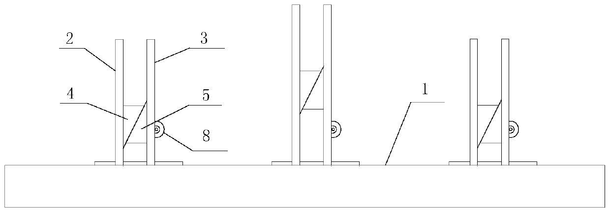
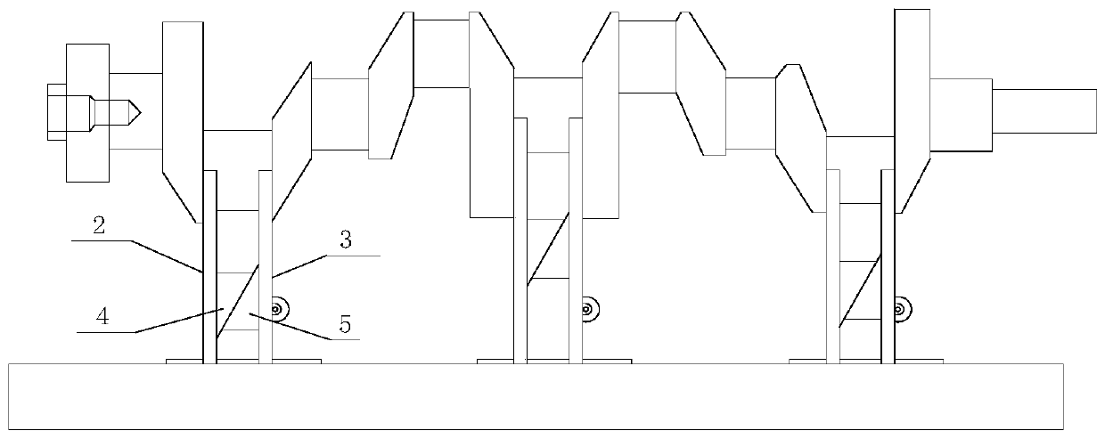
[0030] The opposite plate surface of the second side pressing plate 3 and the first side pressing plate 2 is provided with a vertically extending chute and a rack that can slide up and down in the chute, and the tooth surface of the rack faces away from the first side. One side of the pressing plate 2; the side of the second side pressing plate 3 away from the first side pressing plate 2 is provided with a window communicated with the chute and a gear 8 that is rotatably installed at the window; the gear 8 meshes with the rack, and the second inclined block 5 Fixed with the rack. When the gear 8 rotates, the second inclined block 5 can be promoted to move up and down. And in order to facilitate the rotation of the gear 8, a crank handle is provided on the gear 8 in the present embodiment.

Embodiment 2

[0032] refer to Figure 4 , the second side pressure plate 3 is provided with a vertically extending chute and a slide block that is located in the chute and slides with the chute on the opposite plate surface of the first side pressure plate 2; the second side pressure plate 3 is far away from the first side pressure plate One side of 2 is fixed with the slider. The second slanting block 5 is provided with a connecting portion 6 fixed thereto, and the connecting portion 6 is provided with a fastening bolt 7 threadedly engaged with it, and one end of the fastening bolt 7 abuts against the second side pressure plate 3 . To lock the second oblique block 5. In this embodiment, the connecting portion 6 is opposite to the side of the second side pressure plate 3 to facilitate the screwing in and out of the fastening bolt 9 .


PUM


Abstract

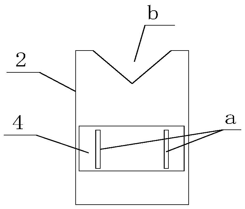
The invention discloses a universal type crankshaft fixture. The universal type crankshaft fixture comprises a base and multiple clamping assemblies mounted on the base, wherein each clamping assemblycomprises a first side press plate and a second side press plate, the first side press plate and the second side press plate are mounted on the base in a sliding manner respectively, the first side press plate is arranged opposite to the second side press plate, a first sloping block fixed with the first side press plate is arranged on the plate surface, opposite to the second side press plate, of the first side press plate, and a second sloping block capable of sliding up and down is arranged on the plate surface, opposite to the first side press plate, of the second side press plate; and the inclined direction of the inclined plane of the first sloping block is opposite to that of the inclined plane of the second sloping block, and the inclined plane of the first sloping block and the inclined plane of the second sloping block are attached and are in sliding connection. The universal type crankshaft fixture has good universality.

Description

technical field [0001] The invention relates to the technical field of crankcases, in particular to a universal crankshaft clamp. Background technique [0002] The crankshaft is the most important component in the engine. It bears the force transmitted by the connecting rod and converts it into torque through the crankshaft output and drives other accessories on the engine to work. The crankshaft needs to be fixed with a fixture in advance during processing. However, due to crankshafts of different specifications, the journal lengths are different. However, the existing fixtures either have complex structures and numerous processes during clamping, or cannot meet the fixing requirements of crankshafts of different specifications. Contents of the invention [0003] In order to solve the technical problems existing in the background technology, the present invention proposes a universal crankshaft clamp. [0004] A universal crankshaft clamp proposed by the present inven...

Claims


Application Information

Patent Timeline
Patent Type & Authority Applications(China)
IPC IPC(8): B25B11/00
CPCB25B11/00
Inventor 李瑞林袁新宇冯冬徐新元
Owner WUHU RUIHE ELECTROMECHANICAL
Learn More