A new energy vehicle charging pile

A technology of new energy vehicles and charging piles, applied in electric vehicle charging technology, charging stations, electric vehicles, etc., can solve problems such as troublesome maintenance, single connection between cables and interfaces, and insensitive charging interfaces, etc., to prolong the service life , Guarantee normal power supply and good protection effect

Active Publication Date: 2022-04-08
杨英
View PDF0 Cites 0 Cited by
  • Summary
  • Abstract
  • Description
  • Claims
  • Application Information

AI Technical Summary

Problems solved by technology

The charging pile uses the charging gun to charge the electric vehicle through the cable. During the charging process, the charging gun drags the cable according to the parking distance of the car. Due to the single connection between the cable and the interface and the lack of protective facilities, the long-term towing During the process, the cable is prone to bending and loosening at the interface. After a long time, the charging interface will be insensitive, affecting the normal supply of electricity, and maintenance is more troublesome.

Method used


Image

  • A new energy vehicle charging pile
  • A new energy vehicle charging pile
  • A new energy vehicle charging pile

Examples


Embodiment 1

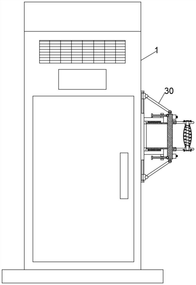
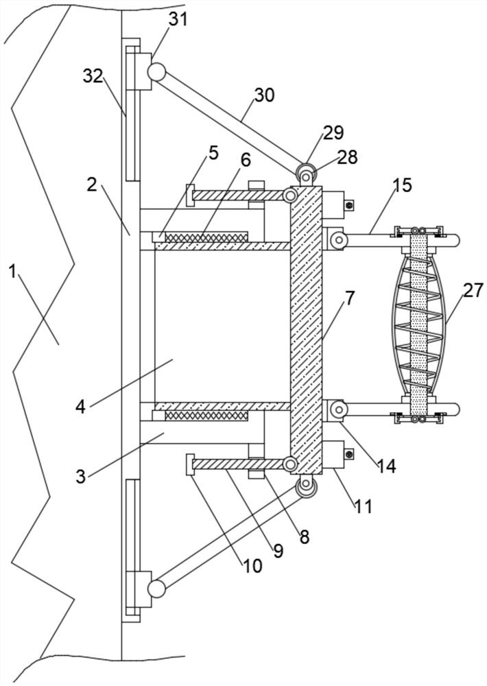
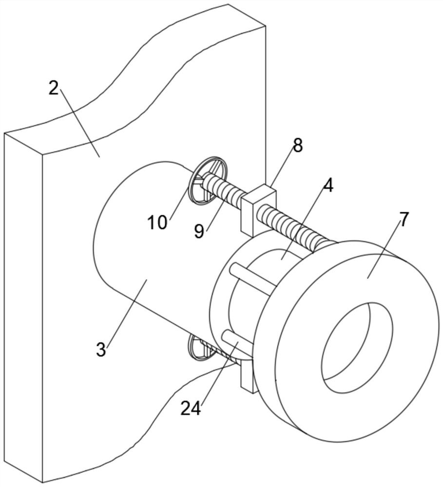
[0026] Including the charging pile body 1, one side of the charging pile body 1 is provided with an interface, one side of the interface is provided with a substrate 2, the substrate 2 is fixed on the charging pile body 1, and the middle part of the substrate 2 is provided with an opening, and one of the openings is There is a telescopic adjustment mechanism on one side, and a protective mechanism on one side of the telescopic adjustment mechanism;

[0027] The telescoping adjustment mechanism includes a first cylinder 3, the first cylinder 3 is fixed on one side of the base plate 2, the inside of the first cylinder 3 is slidably inserted and connected with a second cylinder 4, and both sides of the second cylinder 4 are A slider 5 is fixedly provided, and the two sliders 5 are respectively connected to the slots provided on the inner wall of the first cylinder 3. One side of the slider 5 is fixedly provided with a first spring 6, and one end of the first spring 6 is connected ...

Embodiment 2

[0034]The protection mechanism comprises two mounts 14, and the two mounts 14 are respectively fixed on the top and bottom of the other side of the spacer ring 7, and one side of the mount 14 is movably connected with a supporting plate 15, and the two supporting plates 15 There are two piercing rods 16 between them, the supporting plate 15 is provided with a perforation opposite to the piercing rod 16, both ends of the piercing rod 16 are provided with a limit mechanism, and the outer part of the piercing rod 16 is provided with a third spring 26 , both ends of the third spring 26 are fixedly provided with slip rings 25, the slip rings 25 are slidably connected to the outside of the rod 16, the outside of the third spring 26 is sleeved with a protective cover 27, and the two ends of the protective cover 27 are respectively connected to the two One end of a slip ring 25 is fixedly connected, one side of the mounting seat 14 is provided with a concave plate 11, the concave plate...


PUM


Abstract

The invention discloses a new energy vehicle charging pile, which comprises a charging pile body, an interface is provided on one side of the charging pile body, a substrate is arranged on one side of the interface, the substrate is fixed on the charging pile body, and an opening is provided in the middle of the substrate. A telescopic adjustment mechanism is provided on one side of the opening, and a protective mechanism is provided on one side of the telescopic adjustment mechanism. The telescopic adjustment mechanism includes a first cylinder, which is fixed on one side of the substrate, and The inside is slidably interspersed with a second cylinder, both sides of the second cylinder are fixed with sliders, one end of the second cylinder is fixed with a limit ring, and the top and bottom of one side of the limit ring are equipped with positioning mechanisms . The invention supports the cable and the interface through the telescopic adjustment mechanism, adjusts the length according to the dragging of the cable, and uses the protection mechanism to protect the bending part of the cable to reduce the bending of the cable and the interface , to ensure that the connection between the cable and the interface is sensitive, and to ensure the normal power supply of the charging pile.

Description

technical field [0001] The invention relates to the field of charging piles, in particular to a charging pile for new energy vehicles. Background technique [0002] As an energy supply device for electric vehicles, the charging performance of electric vehicle charging piles is related to the service life and charging time of the battery pack, which is also one of the most concerned aspects of consumers before purchasing electric vehicles. , Safe and reasonable power supply is the basic principle of electric vehicle charger design. In addition, the applicability of the charger to various power batteries must also be considered. The charging pile uses the charging gun to charge the electric vehicle through the cable. During the charging process, the charging gun drags the cable according to the parking distance of the car. Due to the single connection between the cable and the interface and the lack of protective facilities, the long-term towing During the process, the cable ...

Claims


Application Information

Patent Timeline
Patent Type & Authority Patents(China)
IPC IPC(8): B60L53/31B60L53/18
CPCB60L53/31B60L53/18Y02T10/70Y02T10/7072Y02T90/12Y02T90/14
Inventor 杨英
Owner 杨英
Why Eureka
Try Eureka