A high-speed railway track condition dynamic monitoring device
A technology for dynamic monitoring and high-speed railways. It is applied in the direction of railway vehicle shape measuring devices, railway car body parts, railway auxiliary equipment, etc. It can solve problems such as analyzing whether there is a fault, unable to cope with dynamic monitoring, and unable to reflect changes in high-speed trains. , to achieve the effect of improving monitoring accuracy, achieving pertinence and comprehensive risk
- Summary
- Abstract
- Description
- Claims
- Application Information
AI Technical Summary
Problems solved by technology
Method used
Image
Examples
Embodiment 1
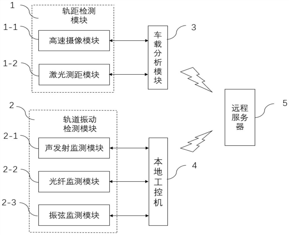
[0028] A high-speed railway track condition dynamic monitoring device, comprising a gauge detection module 1 and a vehicle-mounted analysis module 3 connected thereto, a track vibration detection module 2 and a local industrial computer 4 connected thereto, and a remote server 5; the remote server 5 They are respectively connected to the on-board analysis module 3 and the local industrial computer 4 for communication.
[0029]The gauge detection module 1 includes a high-speed camera module 1-1 and a laser distance measuring module 1-2; the high-speed camera module 1-1 and the laser distance measuring module 1-2 are all connected with the on-board analysis module 3, and the high-speed The camera module 1-1 is installed at the bottom of the train to take pictures of the train wheels and tracks; the laser distance measuring module 1-2 is installed on two opposite wheel hubs, and the distance between the two hubs is measured multiple times by means of opposite shots, and then the d...
Embodiment 2
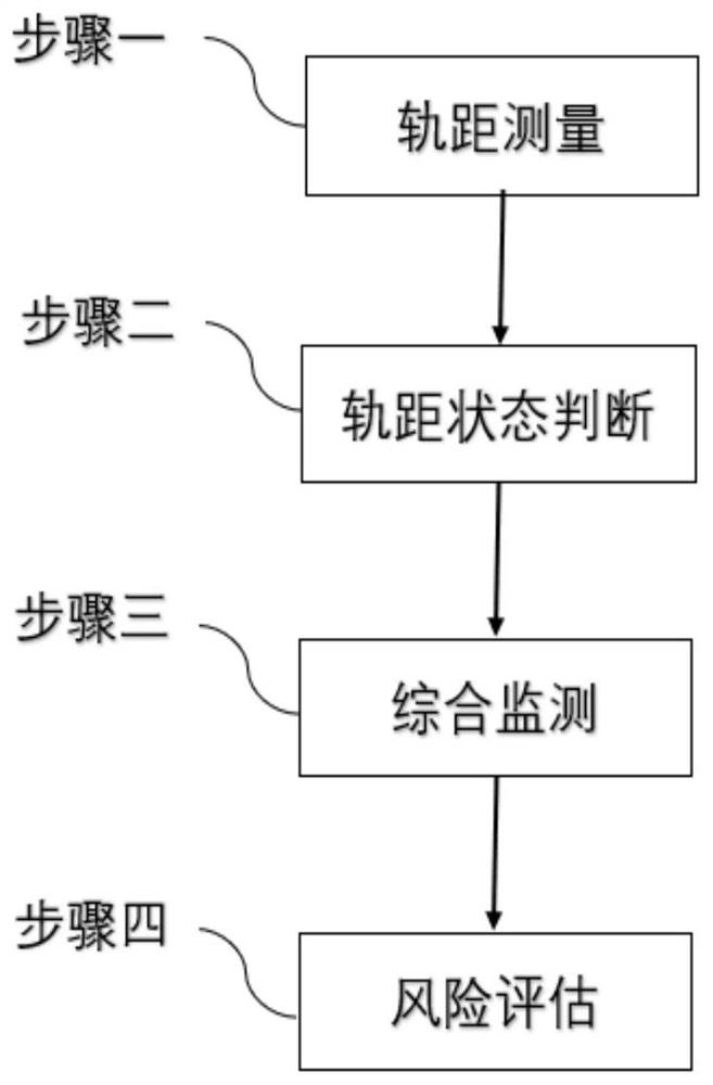
[0038] A method for dynamic monitoring of high-speed railway track conditions, using the above-mentioned device, and comprising the following steps:
[0039] Step 1. Gauge measurement: use the laser ranging module 1-2 installed on the two opposite wheel hubs to measure the distance between the two hubs multiple times to calculate the gauge, and start the high-speed camera module 1-1 when the gauge exceeds the preset threshold Take multiple images of train wheels and tracks;
[0040] Step 2. Judgment of gauge state: extract the image features of the rails and wheels from the multiple pictures of the train wheels and tracks taken, and then judge whether the rails are in an abnormal deformation state;
[0041] Step 3, comprehensive monitoring: record the corresponding position when it is judged that the rail is in an abnormally deformed state, and further monitor the rail. The further monitoring includes the monitoring of internal defects of the rail, track vibration and the foun...
Embodiment 3
[0044] In this embodiment, others are the same as Embodiment 2, and the difference is that the step of judging whether the rail is in an abnormally deformed state in said step 2 is specifically:
[0045] Extract the image features of the rails and wheels from the captured images, the image features include texture features, shape features and local feature points, use the BRJEF algorithm to select several pixel point pairs in the field around the feature points of the rails and wheels, and pass Compare the gray values of these point pairs with the gray values of the normal rails and wheels in the database, and then obtain a concatenated binary bit string to describe each feature point, and use the Hamming distance to calculate the gray values of the rails and wheels Whether the value exceeds the threshold to determine whether the rail is in an abnormal deformation state.
PUM
 Abstract
Description
Claims
Application Information
 - R&D
- Intellectual Property
- Life Sciences
- Materials
- Tech Scout
- Unparalleled Data Quality
- Higher Quality Content
- 60% Fewer Hallucinations
Browse by: Latest US Patents, China's latest patents, Technical Efficacy Thesaurus, Application Domain, Technology Topic, Popular Technical Reports.
© 2025 PatSnap. All rights reserved.Legal|Privacy policy|Modern Slavery Act Transparency Statement|Sitemap|About US| Contact US: help@patsnap.com


