Supercharge Your Innovation With Domain-Expert AI Agents!

Novel slip structure

A slip structure and a new type of technology, applied in drilling equipment, earthwork drilling, drill pipe, etc., can solve problems such as cracks in the pin hole position of the rib plate, and achieve the effect of improving the clamping effect.

Active Publication Date: 2020-08-25
CHONGQING UNIVERSITY OF SCIENCE AND TECHNOLOGY
View PDF5 Cites 0 Cited by
  • Summary
  • Abstract
  • Description
  • Claims
  • Application Information

AI Technical Summary

Problems solved by technology

The traditional slip ribs are directly against the outer wall of the slips, and when the slips are subjected to the clamping force, the maximum equivalent stress is less than the allowable stress, so its structural strength meets the actual use requirements; but the When the structure acts on the pipeline, the stress is t

Method used


Image

  • Novel slip structure
  • Novel slip structure
  • Novel slip structure

Examples


Embodiment Construction

[0035] The present invention will be further described below in conjunction with embodiment and accompanying drawing.

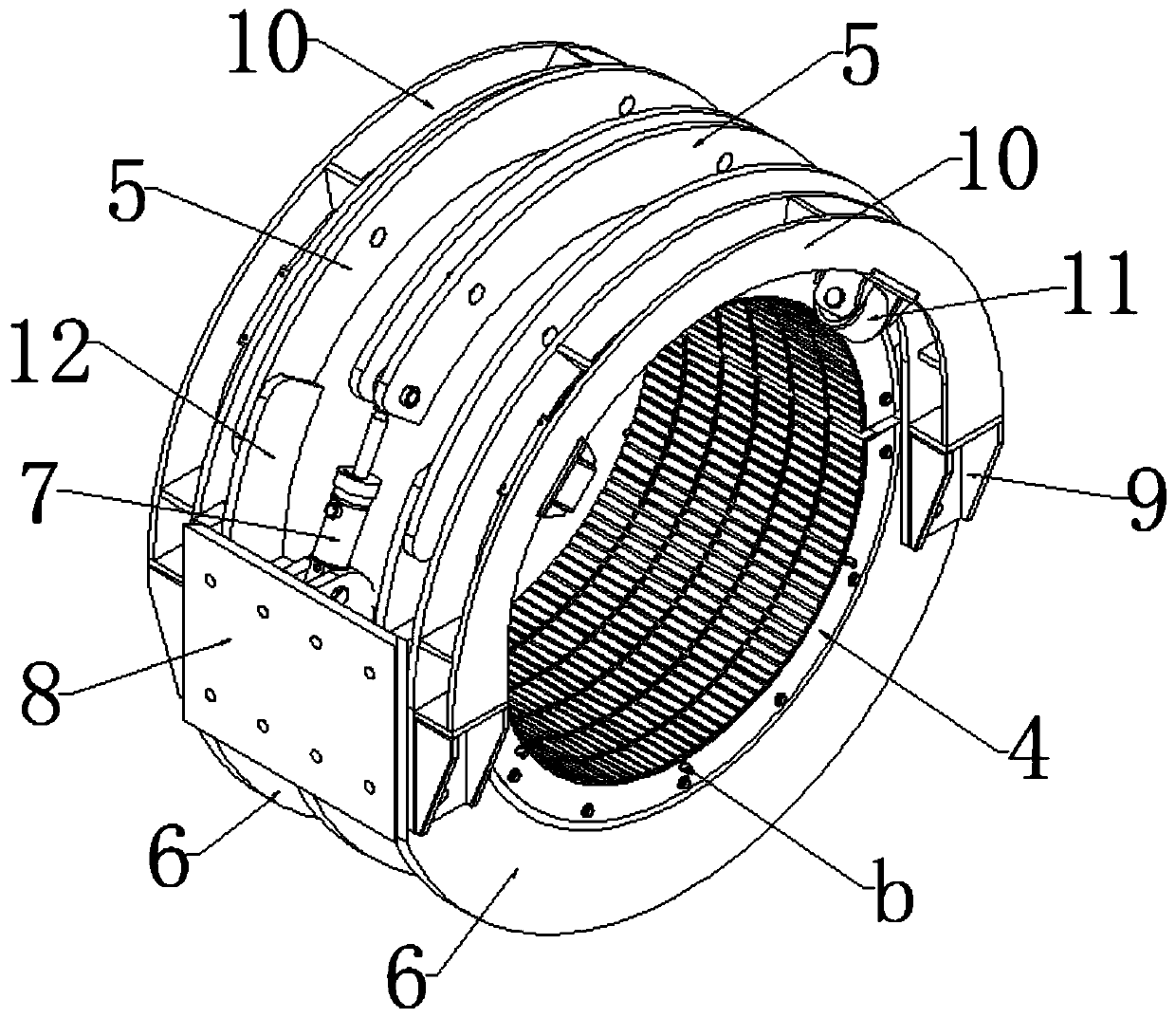
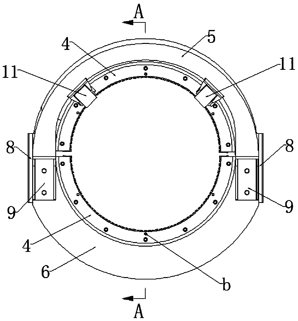
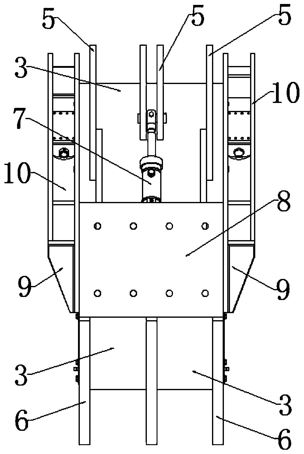
[0036] Such as Figure 1 to Figure 6 As shown, a new type of slip structure, which mainly includes a slip body, a hoop plate and a hoop ring, the slip body, the hoop plate and the hoop ring are all ring structures, and the hoop plate cover It is arranged on the slip body, the inner ring of the hoop plate fits the outer ring of the slip body, and the hoop ring is set on the hoop plate;

[0037] The slip body includes two slip plates 1, the two slip plates 1 are arc-shaped structures, the inner arc surfaces of the two slip plates 1 are arranged facing each other, and the two slip plates 1 A clamping area is formed between them, and at least two arc-shaped pressure plates 2 are arranged on the outer arc surface of the slip plate 1, and the inner arc surface of the arc-shaped pressure plate 2 and the corresponding outer arc of the slip plate 1 surface fit;

[...


PUM


Abstract

The invention discloses a novel slip structure. The novel slip structure comprises a slip body, a hoop plate and a hoop ring, wherein the slip body, the hoop plate and the hoop ring are all of annularstructures, the hoop plate is arranged on the slip body in a sleeving mode, the hoop ring is arranged on the hoop plate in a sleeving mode, the slip body comprises two slip plates, a clamping area isformed between the two slip plates, at least two arc-shaped pressing plates are arranged on each of the outer arc faces of the slip plates, the hoop plate comprises two arc-shaped hoop plates, at least two butt joint grooves are formed in each of the inner arc faces of the arc-shaped hoop plates, the butt joint grooves correspond to the arc-shaped pressing plates in a one-to-one mode, and the arc-shaped pressing plates fall into the corresponding butt joint grooves. By the adoption of the novel slip structure, when enclasping force is exerted on a pipeline, stress acting on the pipeline is evenly distributed, in the clamping process, the hoop plate exists between slips and enclasping rib plates, the stress can be evenly transmitted to the surface of the clamped pipeline through the slips,the enclasping rib plates are prevented from making direct contact with the slip plates, and the clamping effect is effectively improved.

Description

technical field [0001] The invention relates to a clamping slip structure, in particular to a novel slip structure. Background technique [0002] The pipe pushing machine plays an important role in pushing the pipe in long-distance and large-diameter horizontal directional drilling. During the pipe pushing process, it is necessary to push the pipe tightly. The pipe is usually clamped by slips. Hold on tight. The traditional slip ribs are directly against the outer wall of the slips, and when the slips are subjected to the clamping force, the maximum equivalent stress is less than the allowable stress, so its structural strength meets the actual use requirements; but the When the structure acts on the pipeline, the stress is too concentrated, and it is very easy to crack at the position of the pin hole of the rib plate during the long-term work process, and the traditional slips do not transmit the stress to the pipeline evenly through the slips during the tightening process...

Claims


Application Information

Patent Timeline
IPC IPC(8): E21B19/10
CPCE21B19/10
Inventor 肖鑫源邓晓刚魏秦文李泓林伟坚王晓倩刘洋
Owner CHONGQING UNIVERSITY OF SCIENCE AND TECHNOLOGY
Features
  • R&D
  • Intellectual Property
  • Life Sciences
  • Materials
  • Tech Scout
  • Unparalleled Data Quality
  • Higher Quality Content
  • 60% Fewer Hallucinations
Learn More