Light sensation test calibration method and device and electronic equipment

A calibration method and technology of equipment to be tested, applied in measurement devices, photometry, optical radiation measurement, etc., can solve the problems of low production efficiency, many manual operations, complicated operations, etc., to improve production efficiency, improve accuracy and adaptive effect

Pending Publication Date: 2020-08-25
SHANGHAI WINGTECH INFORMATION TECH CO LTD
6 Cites 0 Cited by

AI-Extracted Technical Summary

Problems solved by technology

In the existing light sensing test, the operator needs to connect the device to the test equipment through the connecting line, and then perform ...

Abstract

The invention provides a light sensation test calibration method and device and electronic equipment and relates to the field of automation control, and the method comprises the steps that firstly, adevice to be tested is placed at a position to be calibrated of a light sensation test area, the light sensation test area is provided with a fixed clamping plate and a preset calibration pattern, thefixed clamping plate is used for fixing the device to be tested, and the calibration pattern is used for calibrating the device to be tested; and then a camera in the device to be tested for photographing is started to obtain a photographing result; whether the photographing result contains a calibration pattern or not is judged; and if so, the device to be tested is successfully calibrated, anda light sensation test is executed. According to the method, the positions of the fixed clamping plate and the to-be-calibrated area are relatively fixed; the calibration process can be realized by starting the camera in the to-be-tested equipment to identify the calibration pattern, and the process can be realized by automatically triggering the photographing process in the device to be tested, so that the operation of plugging and unplugging a connecting wire, clicking a test button and the like by an operator in the traditional calibration process is avoided, and the production efficiency is improved.

Application Domain

Photometry

Technology Topic

EngineeringLight sensing +3

Image

  • Light sensation test calibration method and device and electronic equipment
  • Light sensation test calibration method and device and electronic equipment
  • Light sensation test calibration method and device and electronic equipment

Examples

  • Experimental program(1)

Example Embodiment

[0037] In order to make the objectives, technical solutions, and advantages of the embodiments of the present invention clearer, the technical solutions of the present invention will be described clearly and completely with reference to the accompanying drawings. Obviously, the described embodiments are part of the embodiments of the present invention, not all of them. 的实施例。 Example. Based on the embodiments of the present invention, all other embodiments obtained by those of ordinary skill in the art without creative work shall fall within the protection scope of the present invention.
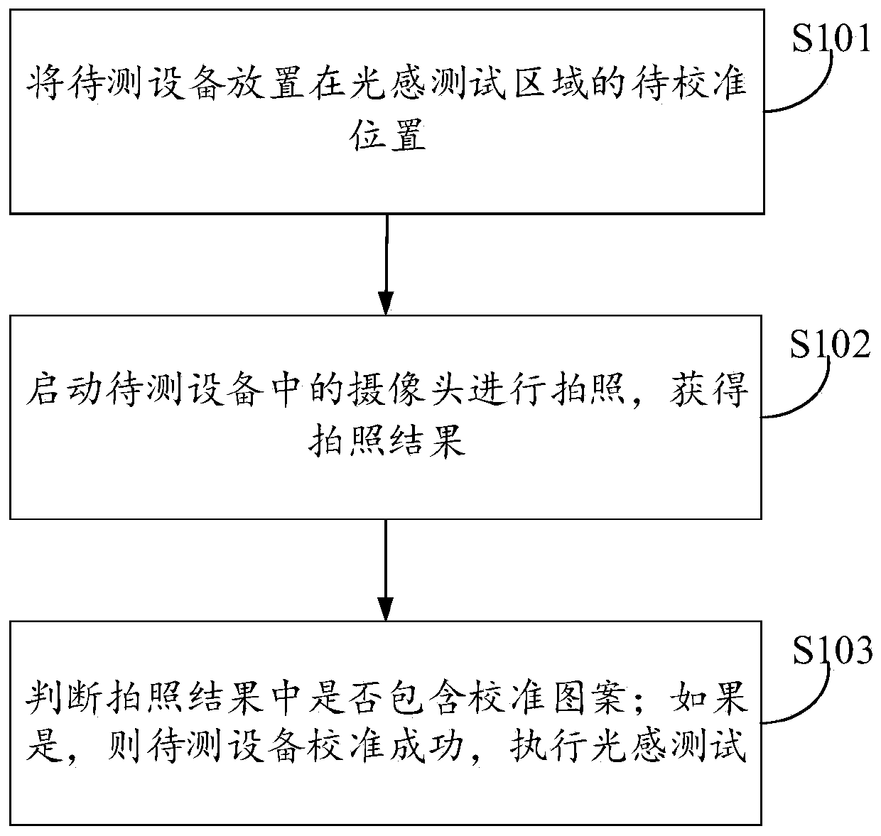
[0038] The light sensing device in the smart device is a component used to sense the surrounding light, through which the intensity of the surrounding light can be obtained to control the brightness of the screen, which is usually used in smart phones and laptops. Due to the high sensitivity and integration of light sensing devices, strict testing is required during the production process. Once a poor light sensing device is assembled into a smart device, the subsequent disassembly and replacement process is more cumbersome, and it is easy to cause other components. Therefore, the testing of light-sensitive devices becomes very important.
[0039] In the testing process of the existing light sensing device, it is necessary to connect the smart device to be tested through a data line, and then to test the light sensing through a dedicated light sensing test machine. The light sensing tester is equipped with a standard light source, and the brightness of the standard light source is controlled through related programs to test the light sensing of the smart device under test. In the above process, how to ensure the alignment between the light source and the light-sensing light-permeable hole in the smart device to be tested becomes very important. Because once there is a deviation, the light emitted by the standard light source cannot be correctly received by the light sensing device, which affects the test accuracy. It can be seen that the calibration of the smart device under test is an important part of the light sensing device test.
[0040] The existing calibration process is mainly carried out manually. The operator needs to connect the equipment to the light-sensing tester through a connection line, and then perform the light-sensing test after calibration. This process requires more manual operations, complex operations, and higher production efficiency. low. As smart devices include mobile phones, laptops, and many other types, the types of cables used are also different, and compatibility is poor, which affects production efficiency.
[0041] Taking into account the above-mentioned problems in the light sensing test calibration process in the existing smart device manufacturing process, the purpose of the present invention is to provide a light sensing test calibration method, device and electronic equipment. This technology can be applied to the light sensing test calibration process. In the process, relevant software or hardware can be used to implement the process, which is described in the following embodiments.
[0042] In order to facilitate the understanding of this embodiment, firstly, a light-sensing test calibration method of placing the device under test at the position to be calibrated in the light-sensing test area disclosed in the embodiment of the present invention is introduced in detail. The flowchart of the method is as follows: figure 1 Shown, including:
[0043] In step S101, the device to be tested is placed at the position to be calibrated in the light sensing test area.
[0044] The devices to be tested can be smart phones, laptops, tablets, and other smart devices. These devices have built-in light sensors. In the process of generating these smart devices, the built-in light sensors need to be tested. The light sensor in the device to be tested is usually set down on the screen panel, and the surrounding light is collected through the light-transmitting hole provided in the screen panel.
[0045] In the specific light sensing test process, the device under test needs to be placed in a dedicated light sensing test machine for testing. The light sensing test machine is equipped with a standard light source, and the brightness of the standard light source is controlled through related programs to control the smart device under test. Light perception is tested. During the testing process, the light-sensing light-permeable hole of the device under test is small, so the standard light source of the light-sensing test machine and the light-sensing light hole of the device under test need to be rigorously calibrated to ensure the accuracy of the test.
[0046] The light sensing test area is the placement area of ​​the device to be tested, and the fixed splint and the preset calibration pattern are arranged in this area. The fixing splint is used to fix the device under test so that the light-sensing hole of the device under test can be roughly aligned with the standard light source; the calibration pattern is used to calibrate the device under test, and the standard pattern is set in the camera shooting area at the position of the standard pattern It is fixed and convenient for shooting when the device under test is being tested. The calibration pattern can be selected according to actual needs, such as a two-dimensional code, an arrow, and a regular pattern.
[0047] Due to the large number of types of equipment under test, different types of equipment under test need to be fixed to the light-sensing tester according to their own size. For example, the size of a mobile phone and a notebook computer are quite different, and each special fixing plate is required for fixing. And because of different types of equipment under test, the camera lens parameters are also different, so the setting position of the standard pattern also needs to be adjusted according to different types.
[0048] In step S102, the camera in the device under test is started to take a photo, and the photo result is obtained.
[0049] When the device under test is placed in the light sensing tester, the camera of the device under test is started to take pictures. The timing of activation is controlled by a program, which can be set in the light-sensing tester or the device under test.
[0050] Specifically, the trigger timing of the camera in the device under test can be executed by a built-in test program. In the production process of the assembly line, the camera in the device under test can be triggered to take a photo when entering the light sensing test. Since it takes a certain amount of time for the device under test to enter the light-sensing tester, it can be triggered by continuous shooting after triggering the shooting. If the time interval is set too long, the waiting time for shooting will be longer, which affects the test efficiency; and If the time interval is set decisively, more useless photos will be taken, resulting in more junk files. Therefore, the time interval for continuous shooting is set according to the actual scene.
[0051] Step S103: It is judged whether a calibration pattern is included in the photographing result; if it is, the device under test is successfully calibrated and a light sensing test is performed.
[0052] The judgment process is realized by using the relevant recognition algorithm. In the specific implementation process, the autofocus algorithm in the device under test can be used to focus first, and then the recognition can be performed after obtaining a clear standard pattern. If the calibration image is not included in the photographing result, the result obtained by the autofocus algorithm is different from the expected result, and the result of unsuccessful calibration can be obtained.
[0053] Since the shooting area contains the calibration pattern, it is bound to include the calibration pattern in the photographing results obtained under normal circumstances. After recognizing the calibration pattern, if the result obtained contains the calibration pattern, it indicates that the device under test is successfully calibrated and the light sensing test is performed.
[0054] In the light sensing test calibration method mentioned in the embodiment of the present invention, it can be known that the position of the fixed splint and the area to be calibrated in this method are relatively fixed. Calibration can be achieved by activating the camera in the device under test to recognize the calibration pattern. Process, the above process can be realized by automatically triggering the photographing process in the device under test, which avoids the need for the operator to plug and unplug the connection line and click the test button in the traditional calibration process, thereby improving production efficiency.
[0055] In some embodiments, after the step S103 of determining whether a calibration pattern is included in the photographing result, the method further includes:
[0056] If not, return to the step of placing the device under test at the position to be calibrated in the light sensing test area.
[0057] If it is judged that the calibration pattern is not included in the photographing result, it indicates that the placement position of the device under test does not meet the requirements of the light sensing test and needs to be placed again. In the specific implementation process of the production line, if the calibration pattern is not recognized, the light sensor tester or the device under test will give an alarm. The operator can inspect the device under test, and manually place the device under test again. Calibrate again.
[0058] In some embodiments, the above-mentioned step S102 of starting the camera in the device under test to take a picture, and obtaining the result of the picture, such as figure 2 Shown, including:
[0059] Step S201: According to a preset shooting interval, a photographing request is sent to the photographing interface in the camera of the device under test.
[0060] This step is realized by the test program in the equipment to be tested. During the specific implementation, the program is installed with the test program during the production process, and the respective test programs are called through the pipeline. Before performing the light sensing test, first calibrate the device. At this time, the test program will cyclically call the API (Application Programming Interface) of the device under test according to the preset shooting interval, so that the The camera in the test equipment takes pictures according to the preset shooting interval.
[0061] The above preset shooting interval is set according to the actual situation. If the time interval is set too long, the waiting time for taking pictures will be longer, which will affect the test efficiency; and if the time interval is set decisively, more useless photos will be taken, resulting in more Many junk files. Therefore, the shooting interval is set to 2 to 3 seconds to meet the needs of most scenes.
[0062] In some embodiments, the camera in the device under test includes one or more of a front camera on the same side of the screen and a rear camera on the opposite side of the screen.
[0063] Due to the different types of devices under test, the camera positions required for taking pictures are also different. For example, a smart phone contains a front camera and a rear camera, and the light sensor is usually near the front camera, so the calibration pattern can be set on the rear camera. The shooting area can also be set in the shooting area of ​​the front camera. For notebook computers, since the camera usually has only one front camera, the standard pattern can only be set in the shooting area of ​​the front camera.
[0064] In step S202, the camera of the device under test receives the photo request, and the camera of the device under test is activated to take a photo, and the photo result is obtained.
[0065] When the camera and photo-related API of the device under test receive a photo request, it can start the device under test to take a photo and obtain the photo result. Since it is an interval shooting, it is necessary to send a photo request to the API in a loop, and the device under test will shoot in a loop at a preset time interval.
[0066] In some embodiments, the step S103 of judging whether a calibration pattern is included in the photographing result, such as image 3 Shown, including:
[0067] Step S301: Invoke the auto-focus interface in the camera of the device under test, and obtain the photo result through the built-in auto-focus recognition algorithm.
[0068] In the process of judging the photographing result, it can be realized by calling the auto-focus interface of the device under test. Specifically, when taking pictures with the camera of the device under test, it is necessary to call the auto-focus interface to complete the focusing operation first, and then perform the test. In this process, the results of autofocus can be initially identified. Since the light-sensing tester is relatively regular, if there is no calibration pattern, it will be difficult for the camera of the device under test to autofocus. Therefore, if the auto-focus is unsuccessful, it means that the device under test has not captured the calibration pattern. Therefore, using the auto-focus recognition algorithm is more convenient and quicker for checking whether the camera result contains the calibration pattern.
[0069] Since the autofocus process has strict requirements on the distance between the camera of the device under test and the shooting physics, in some embodiments, the distance between the calibration pattern and the camera of the device under test is 8-12 cm.
[0070] In the specific implementation process, since the angle of view of the camera in the device under test is usually the angle of view of a standard focal length lens, there is not much difference in the angle of view of the camera lens between different devices under test. At the same time, the size of the calibration pattern is also related to the position where the calibration pattern is arranged, and the size difference of different calibration patterns is not big.
[0071] When the camera lens in the device under test has a wide angle of view, the camera and the calibration pattern need to be closer. In some embodiments, the distance between the calibration pattern and the camera in the device under test may be 8 cm.
[0072] When the angle of view of the camera lens in the device to be tested is a telephoto angle of view, the distance between the camera and the calibration pattern needs to be greater so that the camera can capture the calibration pattern completely in turn. In some embodiments, the distance between the calibration pattern and the camera in the device under test may be 12 cm.
[0073] When the angle of view of the camera lens in the device under test is the standard angle of view (usually equivalent to that of the human eye), the standard angle of view is between the wide-angle angle of view and the telephoto angle of view. Therefore, in some embodiments, the calibration pattern and the angle of view in the device under test The distance between the cameras can be 10 cm.
[0074] In step S302, a recognition algorithm is used to determine whether a calibration pattern is included in the photographing result.
[0075] After the photographing result is obtained, the related recognition algorithm can be used to identify the calibration pattern in the photographing result. The recognition process can be realized by using recognition algorithms in related digital image algorithms, such as color recognition, contour recognition, and text recognition.
[0076] In some embodiments, the aforementioned calibration pattern is a polygon, a two-dimensional code, or a picture containing any pattern. The idea of ​​selecting the calibration pattern is to be as simple as possible, with sharp edges, which is conducive to recognition, and it can also be directly recognized by the two-dimensional code, and directly recognized by reading the information in the two-dimensional code.
[0077] In the light sensing test calibration method mentioned in the above embodiment, the device to be tested is first placed at the position to be calibrated in the light sensing test area, where the light sensing test area is provided with a fixed splint and a preset calibration pattern, and the fixed splint is used for Fix the device under test, and the calibration pattern is used to calibrate the device under test. Then start the camera in the device under test to take a picture and obtain the picture result. Determine whether the calibration pattern is included in the photo result; if it is, the device under test is successfully calibrated and the light sensing test is performed. The position of the fixed splint and the area to be calibrated in this method is relatively fixed. The calibration process can be realized by activating the camera in the device under test to recognize the calibration pattern. The above process can be achieved by automatically triggering the photographing process in the device under test. It is realized that the traditional calibration process also requires the operator to plug and unplug the connection line and click the test button, which improves the production efficiency.
[0078] Corresponding to the embodiment of the light-sensitive test and calibration method, this embodiment also provides a light-sensitive test and calibration device, such as Figure 4 As shown, the device includes:
[0079] The preparation module 401 is used to place the device under test at the position to be calibrated in the light sensing test area; the light sensing test area is provided with a fixed splint and a preset calibration pattern; the fixed splint is used to fix the device under test; the calibration pattern is used to Calibrate the device under test.
[0080] The photographing module 402 is used to start a camera in the device under test to take a photograph and obtain a photographing result.
[0081] The calibration module 403 is used to determine whether a calibration pattern is included in the photographing result; if it is, the device under test is successfully calibrated and the light sensing test is performed.
[0082] In some embodiments, the light sensing test calibration device further includes: a loop execution module, the module is used to determine whether the photographing result contains a calibration pattern; if not, return to the position to be calibrated where the device under test is placed in the light sensing test area A step of.
[0083] In some embodiments, the photographing module 402 further includes:
[0084] The photographing request sending module is used to send a photographing request to the camera photographing interface of the device under test according to the preset photographing interval;
[0085] The photographing execution module is used for receiving the photographing request by the camera of the device under test, starting the camera of the device under test to take a picture, and obtaining the photographing result.
[0086] In some embodiments, the camera in the device under test in the camera module 402 includes one or more of a front camera on the same side of the screen and a rear camera on the opposite side of the screen.
[0087] In some embodiments, the calibration pattern in the aforementioned preparation module 401 is a polygon, a two-dimensional code, or a picture containing any pattern.
[0088] In some embodiments, the distance between the calibration pattern and the camera in the device under test is 8-12 cm.
[0089] In some embodiments, the above-mentioned calibration module 403 includes:
[0090] The auto-focus calling module is used to call the auto-focus interface in the camera of the device under test, and obtain the photo result through the built-in auto-focus recognition algorithm;
[0091] The calibration pattern recognition and calculation module is used to determine whether a calibration pattern is included in the photographing result by using a recognition algorithm.
[0092] The implementation principle and technical effects of the light-sensing test and calibration device provided by the embodiment of the present invention are the same as those of the aforementioned light-sensing test and calibration method. For a brief description, for the parts not mentioned in the embodiment, please refer to the aforementioned method The corresponding content in the embodiment.
[0093] This embodiment also provides an electronic device. A schematic structural diagram of the electronic device is as Figure 5 As shown, the device includes a processor 101 and a memory 102; wherein, the memory 102 is used to store one or more computer instructions, and one or more computer instructions are executed by the processor to implement the aforementioned light sensing test calibration method.
[0094] Figure 5 The electronic device shown further includes a bus 103 and a communication interface 104, and the processor 101, the communication interface 104, and the memory 102 are connected by the bus 103.
[0095] The memory 102 may include a high-speed random access memory (RAM, Random Access Memory), and may also include a non-volatile memory (non-volatile memory), such as at least one disk memory. The bus 103 may be an ISA bus, PCI bus, EISA bus, or the like. The bus can be divided into address bus, data bus, control bus, etc. For ease of presentation, Figure 5 It is represented by only a two-way arrow, but it does not mean that there is only one bus or one type of bus.
[0096] The communication interface 104 is configured to connect to at least one user terminal and other network units through a network interface, and send the encapsulated IPv4 message or IPv4 message to the user terminal through the network interface.
[0097] The processor 101 may be an integrated circuit chip with signal processing capability. In the implementation process, the steps of the foregoing method may be completed by an integrated logic circuit of hardware in the processor 101 or instructions in the form of software. The aforementioned processor 101 may be a general-purpose processor, including a central processing unit (Central Processing Unit, CPU for short), a network processor (Network Processor, NP), etc.; it may also be a Digital Signal Processor (DSP) , Application Specific Integrated Circuit (ASIC), Field-Programmable Gate Array (FPGA) or other programmable logic devices, discrete gates or transistor logic devices, discrete hardware components. The methods, steps, and logical block diagrams disclosed in the embodiments of the present disclosure can be implemented or executed. The general-purpose processor may be a microprocessor or the processor may also be any conventional processor or the like. The steps of the method disclosed in the embodiments of the present disclosure may be directly embodied as being executed and completed by a hardware decoding processor, or executed and completed by a combination of hardware and software modules in the decoding processor. The software module can be located in a mature storage medium in the field, such as random access memory, flash memory, read-only memory, programmable read-only memory, or electrically erasable programmable memory, registers. The storage medium is located in the memory 102, and the processor 101 reads the information in the memory 102, and completes the steps of the method of the foregoing embodiment in combination with its hardware.
[0098] The embodiment of the present invention also provides a computer-readable storage medium having a computer program stored on the computer-readable storage medium, and the computer program executes the steps of the light sensing test calibration method mentioned in the foregoing embodiment when the computer program is run by a processor .
[0099] In the several embodiments provided in this application, it should be understood that the disclosed system, device, and method may be implemented in other ways. The device embodiments described above are merely illustrative, for example, the division of units is only a logical function division, and there may be other divisions in actual implementation. For example, multiple units or components can be combined or integrated. To another system, or some features can be ignored or not implemented. In addition, the displayed or discussed mutual coupling or direct coupling or communication connection may be indirect coupling or communication connection between devices or units through some communication interfaces, and may be in electrical, mechanical or other forms.
[0100] The units described as separate components may or may not be physically separate, and the components displayed as units may or may not be physical units, that is, they may be located in one place, or they may be distributed on multiple network units. Some or all of the units may be selected according to actual needs to achieve the objectives of the solutions of the embodiments.
[0101] In addition, the functional units in each embodiment of the present invention may be integrated into one processing unit, or each unit may exist alone physically, or two or more units may be integrated into one unit.
[0102] If the function is implemented in the form of a software functional unit and sold or used as an independent product, it can be stored in a nonvolatile computer readable storage medium executable by a processor. Based on this understanding, the technical solution of the present invention essentially or the part that contributes to the existing technology or the part of the technical solution can be embodied in the form of a software product, and the computer software product is stored in a storage medium, including Several instructions are used to make a computer device (which may be a personal computer, a server, or a network device, etc.) execute all or part of the steps of the methods in the various embodiments of the present invention. The aforementioned storage media include: U disk, mobile hard disk, read-only memory (ROM, Read-Only Memory), random access memory (RAM, Random Access Memory), magnetic disks or optical disks and other media that can store program codes.
[0103] Finally, it should be noted that the above embodiments are only specific implementations of the present invention, to illustrate the technical solutions of the present invention, rather than limiting them. The protection scope of the present invention is not limited thereto, although referring to the foregoing embodiments The present invention has been described in detail, and those skilled in the art should understand that any person skilled in the art can still modify or modify the technical solutions described in the foregoing embodiments within the technical scope disclosed in the present invention. Easily think of changes, or equivalent replacements of some of the technical features; and these modifications, changes or replacements do not make the essence of the corresponding technical solutions deviate from the spirit and scope of the technical solutions of the embodiments of the present invention, and should be covered by the protection of the present invention Within range. Therefore, the protection scope of the present invention should be subject to the protection scope of the claims.

PUM

no PUM

Description & Claims & Application Information

We can also present the details of the Description, Claims and Application information to help users get a comprehensive understanding of the technical details of the patent, such as background art, summary of invention, brief description of drawings, description of embodiments, and other original content. On the other hand, users can also determine the specific scope of protection of the technology through the list of claims; as well as understand the changes in the life cycle of the technology with the presentation of the patent timeline. Login to view more.

Similar technology patents

Three-dimensional production system of prefabricated components

ActiveCN105773827AIncreased production flexibilityIncrease productivity
Owner:国新德

Precise extrusion molding method of thin wall long-pipe shaped parts bland and special mould

InactiveCN101332476AIncreased dimensional accuracy and material utilizationIncrease productivity
Owner:HENAN UNIV OF SCI & TECH

Method for preparing graphene efficiently

InactiveCN103058176AIncrease productivitylow cost
Owner:HUAQIAO UNIVERSITY +1

Spot welding machine

ActiveCN102114572AIncrease productivityGuarantee spot welding quality
Owner:NINGBO MINTH AUTOMOTIVE PARTS RES&DEV CO LTD

Classification and recommendation of technical efficacy words

  • Increase productivity
  • Improve adaptability and precision

Petrochemical plant inspection robot environment modeling and map building device and method

ActiveCN108181636AImprove adaptability and precisionOvercoming the decline in the quality of mapping
Owner:CHINA UNIV OF MINING & TECH +1

Virtual reality helmet distortion complete machine detection method and device

InactiveCN106644404AImprove adaptability and precisionavoid interference
Owner:VR TECH HLDG LTD
Why Eureka
Try Eureka