Omnidirectional special-shaped bent continuum flexible mechanical arm for intracavity interventional diagnosis and treatment
A flexible robotic arm and continuum technology, applied in the field of medical devices, can solve problems such as the inability to effectively control the maximum bending angle and the complex structure of the continuum robotic arm, so as to reduce the complexity of processing, reduce manufacturing costs, and improve direction positioning capabilities Effect
- Summary
- Abstract
- Description
- Claims
- Application Information
AI Technical Summary
Problems solved by technology
Method used
Image
Examples
Embodiment 1
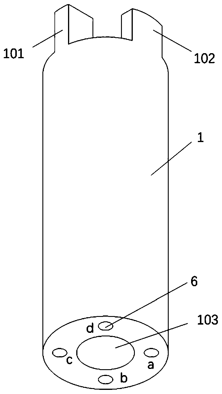
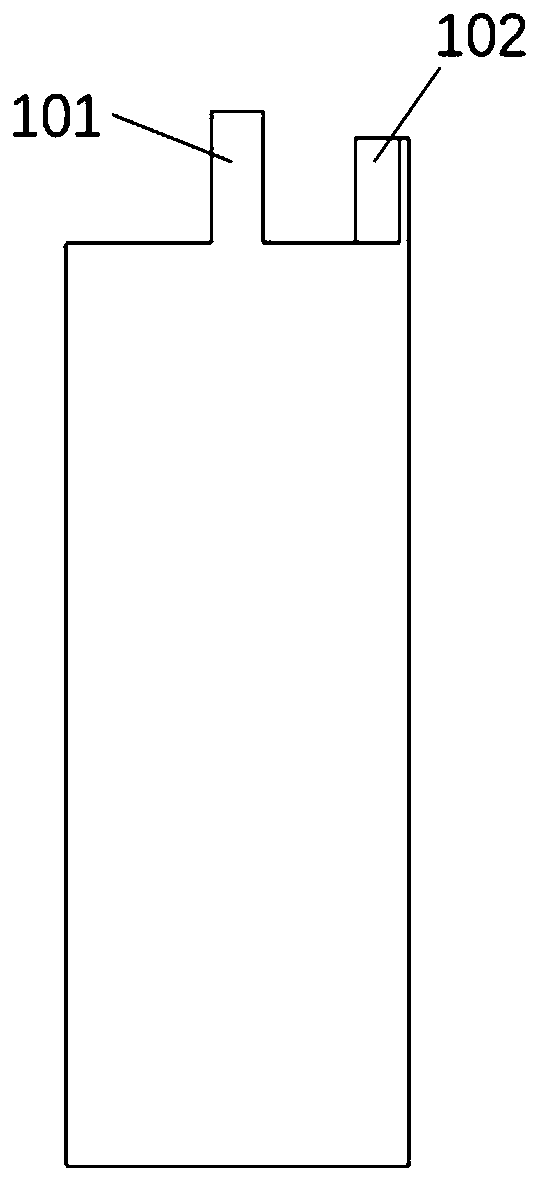
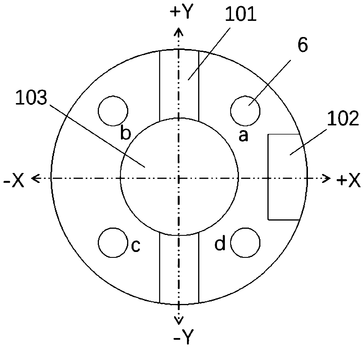
[0065] Such as Figure 1A to Figure 8 As shown, an omnidirectional special-shaped curved continuum flexible robot arm for intracavitary interventional diagnosis and treatment includes a base 1 on which fourteen middle discs 2 and a top disc are arranged from bottom to top 3. The top end of the mechanical arm is the top disc 3, and the bottom end of the mechanical arm is the base 1.
[0066] The center of the base 1 is provided with a first through hole 103, and four wire holes 6 are evenly distributed around the first through hole 103, and the four wire holes 6 are arranged symmetrically with the first through hole 103 as the center; the middle disc The center of 2 is provided with the second through hole 24, and the periphery of the second through hole 24 is provided with four wire holes 6 uniformly distributed, and the four wire holes 6 are arranged symmetrically with the second through hole 24 as the center; The center is provided with a third through hole 31, and four wir...
Embodiment 2
[0079] Embodiment 2 is a modified example of Embodiment 1.
[0080] Such as Figure 1A to Figure 5B , Figure 9 to Figure 14C As shown, in Embodiment 2, the continuum flexible manipulator includes a top disc 3 and nineteen middle discs 2 , the top end of the manipulator is the top disc 3 , and the bottom end of the manipulator is the base 1 .
[0081] The nineteen middle discs 2 are divided into two bilateral spacers 21, seven unilateral spacers 22 and ten thin spacer plates 23.
[0082]Considering the difficulty of processing and manufacturing, while ensuring the smallest possible outer diameter of the manipulator, in this embodiment, the outer diameter of the continuum manipulator is 2.8mm, the height is 47mm, the diameter of the internal middle cavity 5 is 1.4mm, and the nickel-titanium wire hole The diameter of 6 is 0.3 mm, the height of the base 1 is 7 mm, the height of the base frame 101 is 1 mm, and the width is 0.4 mm to ensure greater strain and strength. The height...
Embodiment 3
[0088] Embodiment 3 is a modified example of Embodiment 1.
[0089] Such as Figure 2A to Figure 5B , Figure 15A to Figure 18C As shown, in Embodiment 3, the continuum flexible mechanical arm includes a top disc 3 and nineteen middle discs 2; the top end of the mechanical arm is the top disc 3, the bottom end of the mechanical arm is the base 1, and the base The base 1 has two symmetrically arranged base contact blocks 102, 102'.
[0090] The nineteen middle discs 2 are divided into eight bilateral spacers 21, seven unilateral spacers 22 and four thin spacer plates 23.
[0091] Considering the difficulty of processing and manufacturing, and adapting to the anatomical cavity with a smaller diameter, in this embodiment, the outer diameter of the continuum manipulator is 2.5 mm, the height is 47 mm, the diameter of the internal middle cavity 5 is 1 mm, and the diameter of the nickel-titanium wire hole 6 is The diameter is 0.3mm, the height of the base 1 is 7mm, the height of ...
PUM
 Abstract
Description
Claims
Application Information
 - R&D
- Intellectual Property
- Life Sciences
- Materials
- Tech Scout
- Unparalleled Data Quality
- Higher Quality Content
- 60% Fewer Hallucinations
Browse by: Latest US Patents, China's latest patents, Technical Efficacy Thesaurus, Application Domain, Technology Topic, Popular Technical Reports.
© 2025 PatSnap. All rights reserved.Legal|Privacy policy|Modern Slavery Act Transparency Statement|Sitemap|About US| Contact US: help@patsnap.com


