
Power Electronic Converter Closed-loop Control System

A power electronic conversion and closed-loop control technology, applied in the control/regulation system, regulating electrical variables, converting DC power input to DC power output, etc., can solve problems such as output oscillation, and achieve enhanced stability and reduced periodic oscillation Effect

Active Publication Date: 2021-09-28
UNITED AUTOMOTIVE ELECTRONICS SYST
View PDF5 Cites 0 Cited by
  • Summary
  • Abstract
  • Description
  • Claims
  • Application Information

AI Technical Summary

Problems solved by technology

[0004] The purpose of the present invention is to provide a closed-loop control system of a power electronic converter to solve the problem of output oscillation of the traditional PI regulator compensation link of the existing Buck or Boost converter

Method used


Image

  • Power Electronic Converter Closed-loop Control System
  • Power Electronic Converter Closed-loop Control System
  • Power Electronic Converter Closed-loop Control System

Examples


Embodiment Construction

[0037] The closed-loop control system of the power electronic converter proposed by the present invention will be further described in detail below in conjunction with the accompanying drawings and specific embodiments. Advantages and features of the present invention will be apparent from the following description and claims. It should be noted that all the drawings are in a very simplified form and use imprecise scales, and are only used to facilitate and clearly assist the purpose of illustrating the embodiments of the present invention.

[0038] The core idea of ​​the present invention is to provide a closed-loop control system of a power electronic converter to solve the problem of output oscillation of the traditional PI regulator compensation link of the existing Buck or Boost converter.

[0039] In order to realize the above idea, the present invention provides a closed-loop control system of a power electronic converter, the closed-loop control system of the power ele...


PUM


Abstract

The present invention provides a closed-loop control system of a power electronic converter. The closed-loop control system of the power electronic converter includes an original PI compensation network, a digital trap and a power stage module, wherein: the original PI compensation network is input into a power electronic conversion The difference between the voltage reference value and the voltage actual value of the device; the output value of the original PI compensation network is used as the input value of the digital notch filter, and the pulse coefficient and hysteresis step size of the digital notch filter are configured to suppress the Harmonic oscillation of the power electronic converter; the output value of the digital notch filter is used as the input value of the power stage module; the output value of the power stage module is fed back to the original PI compensation network as the actual voltage value.

Description

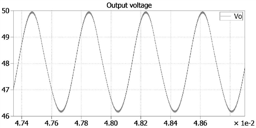
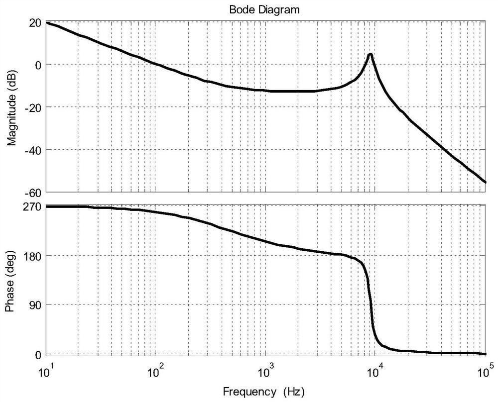
technical field [0001] The invention relates to the technical field of power electronics, in particular to a closed-loop control system of a power electronic converter. Background technique [0002] The power electronic converter is a kind of converter that transmits energy by turning on and off the switching tube. Since its working state is divided into two modes: on and off, it is a nonlinear power conversion device. Due to the complex working conditions of the power electronic converter and the uncertainty of the nonlinear system model, it often encounters phenomena such as bifurcation or chaos, which are manifested as periodic oscillations of voltage and current waveforms and electrical howling. In a power electronic converter, an oscillating voltage waveform such as figure 1 shown. [0003] The common closed-loop control method uses an independent PI regulator as the compensation link, such as figure 2 shown. When the second-order system in the underdamped state is...

Claims


Application Information

Patent Timeline
Patent Type & Authority Patents(China)
IPC IPC(8): H02M3/157
CPCH02M3/157
Inventor 黄昊张建韩炜韩汛峰朱大祥
Owner UNITED AUTOMOTIVE ELECTRONICS SYST
Learn More