
Constant power compensation circuit

A circuit and over-power technology, which is applied in the direction of output power conversion device, AC power input conversion to DC power output, electrical components, etc., can solve the problems of power supply harmonic oscillation and failure to work normally, and achieve the purpose of suppressing harmonic oscillation Effect

Inactive Publication Date: 2019-05-07
NANJING BAIYA INTELLIGENT TECH CO LTD
View PDF0 Cites 1 Cited by
  • Summary
  • Abstract
  • Description
  • Claims
  • Application Information

AI Technical Summary

Problems solved by technology

[0003] In view of this, the present invention provides a constant power compensation method, a compensation circuit and a switching power supply using it, so as to overcome the problem in the prior art that the power supply produces harmonic oscillations, so that it cannot work normally

Method used


Image

  • Constant power compensation circuit
  • Constant power compensation circuit

Examples


Embodiment Construction

[0009] The following will clearly and completely describe the technical solutions in the embodiments of the present invention with reference to the accompanying drawings in the embodiments of the present invention. Obviously, the described embodiments are only some, not all, embodiments of the present invention. Based on the embodiments of the present invention, all other embodiments obtained by persons of ordinary skill in the art without making creative efforts belong to the protection scope of the present invention.

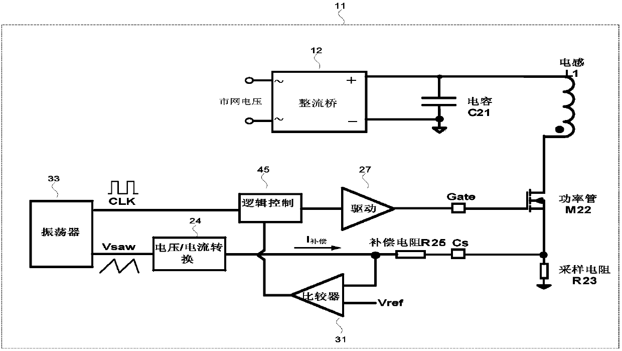
[0010] see figure 1 , which is a realization circuit diagram of a commonly used AC / DC constant power protection circuit in the prior art, the AC / DC constant power protection circuit 11 includes: a rectifier bridge 12, a capacitor C21, an inductor L1, an oscillator 33, a logic control circuit 45, and a drive Circuit 27, voltage / current converter 24, compensation resistor R25, power transistor M22, current comparator 31 and sampling resistor R23.

[0011] Speci...


PUM


Abstract

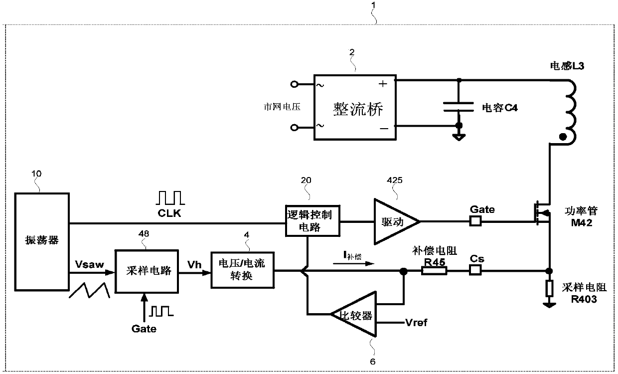
The invention provides a constant power compensation method, which is applied to an AC / DC controller. The AC / DC controller includes a rectifier bridge, a filter capacitor, an inductor, an oscillator,a logic controller, a compensation resistor, a power transistor, a drive circuit, an over-current comparator, a sampling resistor, a sampling circuit and a voltage / current converter. The constant power compensation method includes the steps of collecting the sawtooth wave voltage of the oscillator and holding and sending the collected sawtooth wave voltage to the voltage / current converter. According to the method, the constant power compensation value is kept unchanged in a certain time range instead of transiently changing with the AC / DC drive switching signal, and the occurrence of sub-harmonic oscillation is suppressed.

Description

technical field [0001] The invention relates to the field of AC / DC drivers, more specifically, relates to a constant power compensation method, a compensation circuit and an AC / DC power supply using the same. Background technique [0002] With the rapid development of the electronic information industry, switching power supplies are widely used in computers, electrical equipment, instruments, LED lighting, medical equipment, military equipment and other fields. Usually, a switching power supply converts an external alternating current (such as mains 220V, 380V, etc.) into a stable direct current to supply the load. Switching power supply has many protection functions, such as over-voltage and under-voltage protection, over-temperature protection, over-current protection, over-power protection, etc. These protection functions avoid damage to the power integrated IC and the entire switching power supply. However, in the case of low line voltage and heavy load, the switching ...

Claims


Application Information

Patent Timeline
Patent Type & Authority Applications(China)
IPC IPC(8): H02M7/219H02M1/14
Inventor 不公告发明人
Owner NANJING BAIYA INTELLIGENT TECH CO LTD
Learn More