Unlock instant, AI-driven research and patent intelligence for your innovation.

Digitally controlled monostable trigger and control method thereof

A monostable trigger and digital control technology, applied in the direction of pulse generation, electrical components, electric pulse generation, etc., can solve the problems of adjusting the transient time extensively, unfavorable precise control, etc., and achieve the effect of precise control of the transient time

Active Publication Date: 2020-08-28
NANJING COLLEGE OF INFORMATION TECH
View PDF4 Cites 1 Cited by
  • Summary
  • Abstract
  • Description
  • Claims
  • Application Information

AI Technical Summary

Problems solved by technology

[0003] Aiming at the deficiencies of the prior art, the purpose of the present invention is to provide a digitally controlled monostable trigger and its control method to solve the problem of adjusting the transient state by rotating the adjustment port in the monostable trigger circuit in the prior art. The time is relatively extensive, which is not conducive to precise control of technical issues

Method used


Image

  • Digitally controlled monostable trigger and control method thereof
  • Digitally controlled monostable trigger and control method thereof

Examples


Embodiment Construction

[0021] The present invention will be further described below in conjunction with the drawings. The following embodiments are only used to illustrate the technical solutions of the present invention more clearly, and cannot be used to limit the protection scope of the present invention.

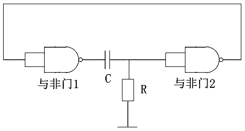
[0022] At present, monostable flip-flops can be divided into monostable flip-flops composed of gate circuits according to the circuit form, MSI integrated monostable flip-flops and monostable flip-flops composed of 555 timers, and monostable composed of CMOS gate circuits. The steady-state trigger is divided into positive pulse trigger and negative pulse trigger. A common simple monostable flip-flop circuit, such as figure 1 Shown is a circuit diagram of a traditional monostable flip-flop mentioned in the embodiment of the present invention. It consists of a NAND gate 1, a capacitor, a resistor, and a NAND gate 2. Its basic working process is as follows: When there is no trigger signal , The cir...


PUM


Abstract

The invention discloses a digitally-controlled monostable trigger and a control method thereof, belongs to the technical field of integrated circuit application, and aims to solve the technical problem that in the prior art, a monostable trigger circuit is relatively extensive in transient state time adjustment in a mode of rotating an adjusting port and is not beneficial to accurate control. Themonostable trigger comprises an NAND gate 1 serving as an input end, an NAND gate 2 serving as an output end, and a digital control circuit electrically connected between the NAND gate 1 and the NANDgate 2. The digital control circuit comprises an NAND gate 3 and an NAND gate 4 which are electrically connected with the NAND gate 1, the NAND gate 3 is electrically connected with the NAND gate 1 through an RC circuit, and the NAND gate 4 is electrically connected with the NAND gate 1 through a counter; the NAND gate 3 and the NAND gate 4 are electrically connected with a NAND gate 5 respectively, and a JK trigger is electrically connected between the NAND gate 5 and the NAND gate 2; and the clock signal input end of the counter is electrically connected with a multivibrator.

Description

Technical field [0001] The invention relates to a digitally controlled monostable trigger and a control method thereof, belonging to the technical field of integrated circuit applications. Background technique [0002] The monostable trigger outputs a low-level trigger signal, which makes the monostable trigger switch from a steady state to a transient state. In the ordinary monostable trigger circuit, the resistor-capacitance circuit (Resistor-Capacitance circuit, RC) is used to charge and discharge, the voltage across the capacitor and the resistor gradually changes, and the NAND gate of the output port of the monostable trigger circuit is affected by When the voltage influence exceeds the threshold, the state of the monostable trigger circuit changes from a transient state to a steady state. The transient time is determined by the time constant of the RC charging and discharging circuit, which is the product of the resistance value and the capacitance value. Once the resista...

Claims


Application Information

Patent Timeline
Patent Type & Authority Applications(China)
IPC IPC(8): H03K3/033H03K3/012
CPCH03K3/033H03K3/012
Inventor 王抗美
Owner NANJING COLLEGE OF INFORMATION TECH