

Convenient-to-adjust overturn type clamping device for machining
A technology of mechanical processing and clamping devices, applied in the direction of workpiece clamping devices, manufacturing tools, etc., can solve problems such as unsatisfactory, not wide application range, clamping range and size restrictions, etc. The effect of working range
- Summary
- Abstract
- Description
- Claims
- Application Information
AI Technical Summary
Problems solved by technology
Method used
Image

Examples
Embodiment 1
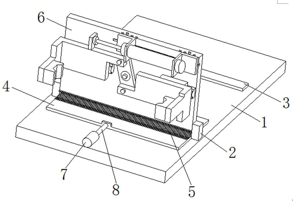
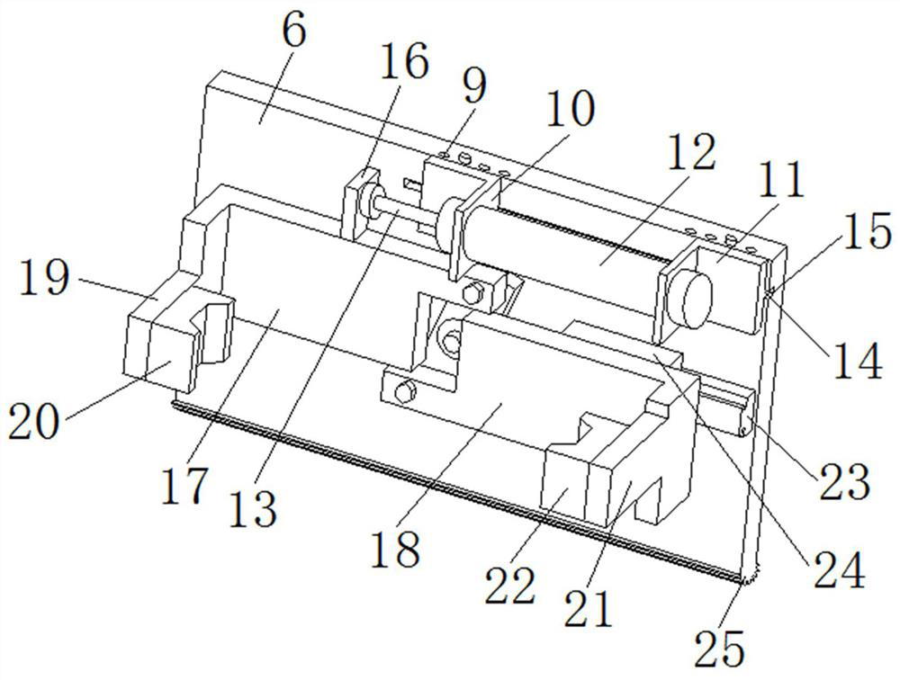
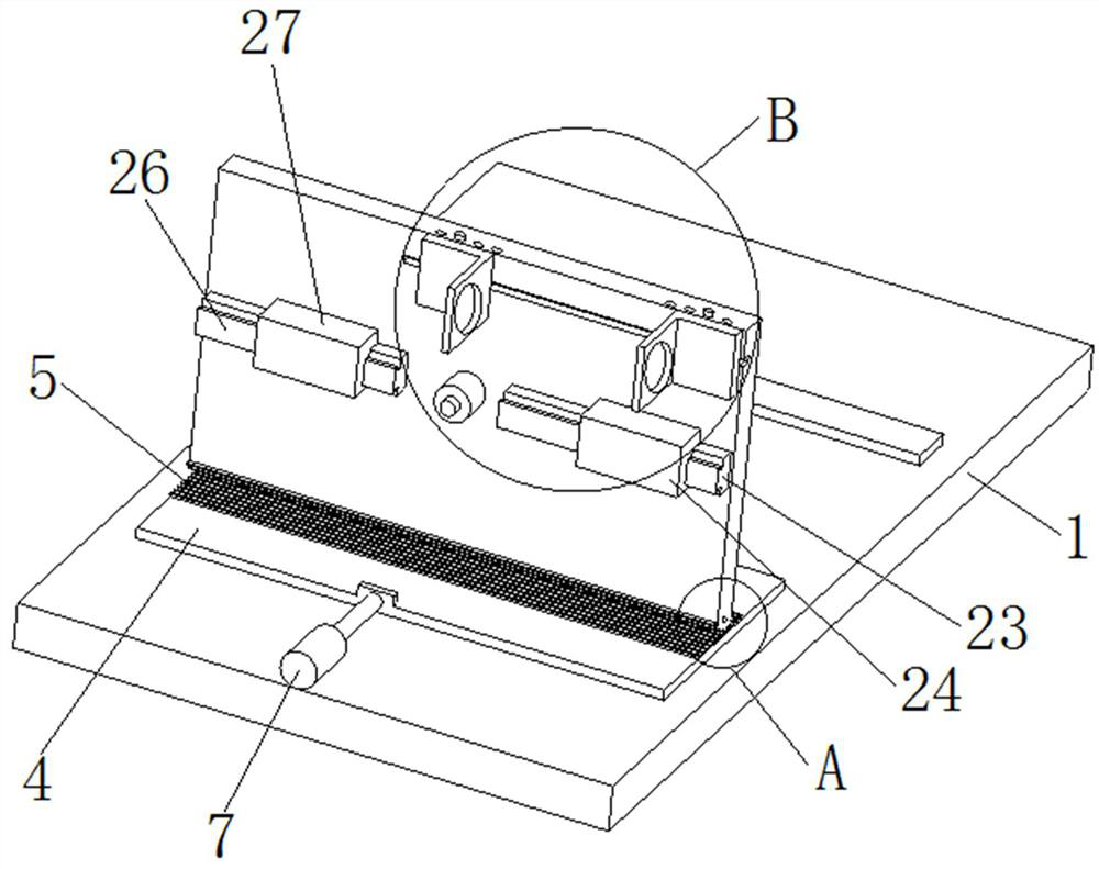
[0028] Such as Figure 1-6 As shown, a flip-type machining clamping device that is easy to adjust includes a bottom plate 1, a support block 2 is fixedly installed on both sides of the upper end of the bottom plate 1, and a clamping shaft is fixedly installed on one side of the support block 2, and two sets of supports A main body plate 6 is arranged between the blocks 2, and both sides of the lower end of the main body plate 6 are provided with clamping holes 34, and the clamping shaft is located in the inside of the clamping hole 34, and the clamping shaft is movably connected with the clamping hole 34, and the bottom end of the main body plate 6 is fixed. A half gear roller 25 is installed, and the lower end of the main body plate 6 is provided with a telescopic plate 4, and the telescopic plate 4 is located between two groups of supporting blocks 2, and a toothed plate 5 is installed on the upper end of the telescopic plate 4, and the toothed plate 5 is located in the half ...
Embodiment 2
[0037] Such as Figure 1-6 As shown, a flip-type machining clamping device that is easy to adjust includes a bottom plate 1, a support block 2 is fixedly installed on both sides of the upper end of the bottom plate 1, and a clamping shaft is fixedly installed on one side of the support block 2, and two sets of supports A main body plate 6 is arranged between the blocks 2, and both sides of the lower end of the main body plate 6 are provided with clamping holes 34, and the clamping shaft is located in the inside of the clamping hole 34, and the clamping shaft is movably connected with the clamping hole 34, and the bottom end of the main body plate 6 is fixed. A half gear roller 25 is installed, and the lower end of the main body plate 6 is provided with a telescopic plate 4, and the telescopic plate 4 is located between two groups of supporting blocks 2, and a toothed plate 5 is installed on the upper end of the telescopic plate 4, and the toothed plate 5 is located in the half ...
PUM
 Abstract
Description
Claims
Application Information