
Spiral core-pulling mechanism of die-casting die

A technology of core-pulling mechanism and die-casting mold, which is applied in the field of die-casting mold equipment, can solve the problems of inconvenient installation, inaccurate starting position of screw teeth, and unsatisfactory use, so as to avoid left and right movement, improve work quality, and facilitate fixed use Effect

Pending Publication Date: 2022-03-25
深圳市超盛金属制品有限公司
View PDF9 Cites 0 Cited by
  • Summary
  • Abstract
  • Description
  • Claims
  • Application Information

AI Technical Summary

Problems solved by technology

[0002] Mold is the abbreviation of a combined mold used for compression molding, extrusion molding, injection molding, blow molding and low foaming molding. Die casting mold is a large category of molds. It is a method of casting liquid forging. It is a process completed on a special die-casting die forging machine. Its basic process is: the molten metal is cast and filled into the cavity of the mold at a low or high speed. The mold has a movable cavity surface, and it cools with the molten metal Process pressure forging not only eliminates the shrinkage cavity and porosity defects of the blank, but also makes the internal structure of the blank reach the broken grains of the forged state. The traditional thread products with starting position requirements are all ordinary spiral core-pulling structures. Assembly The initial position of the thread in the mold cannot be accurately positioned, and the direction of the thread can only be adjusted by using the pre-made marks. This method will lead to inaccurate initial position of the thread, which will affect the quality of the subsequent processed products. In addition , the existing core-pulling structure is not easy to install, and requires extremely high proficiency of assemblers, so it cannot meet the needs of different situations

Method used


Image

  • Spiral core-pulling mechanism of die-casting die
  • Spiral core-pulling mechanism of die-casting die
  • Spiral core-pulling mechanism of die-casting die

Examples


Embodiment approach

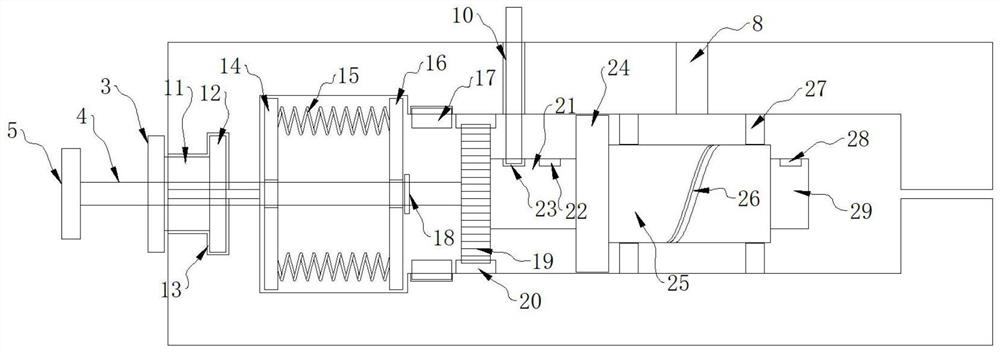
[0026] As a preferred embodiment of the present invention, one side of the baffle plate 14 is fixed with a supporting spring 15, and one end of the supporting spring 15 is fixed with a connecting plate 16, and the connecting plate 16 is installed on the movable column 4, so that A limiting ring 18 is fixed on the movable column 4 , and the limiting ring 18 is matched with the connecting plate 16 .

[0027] As a preferred embodiment of the present invention, a movable ring gear 17 is installed on the inner wall of the cavity, a fixed ring gear 20 is installed on one side of the movable ring gear 17, and a gear is fixed at one end of the movable column 4 19, the gear 19 cooperates with the fixed ring gear 20 and the movable ring gear 17.

[0028] As a preferred embodiment of the present invention, one side of the gear 19 is welded with a support column 21, and the support column 21 is provided with a limiting hole 1 22 and a limiting hole 2 23, and the limiting hole 2 23 and Th...


PUM


Abstract

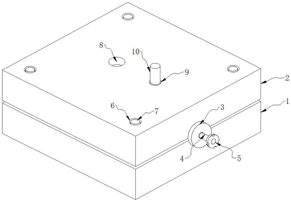
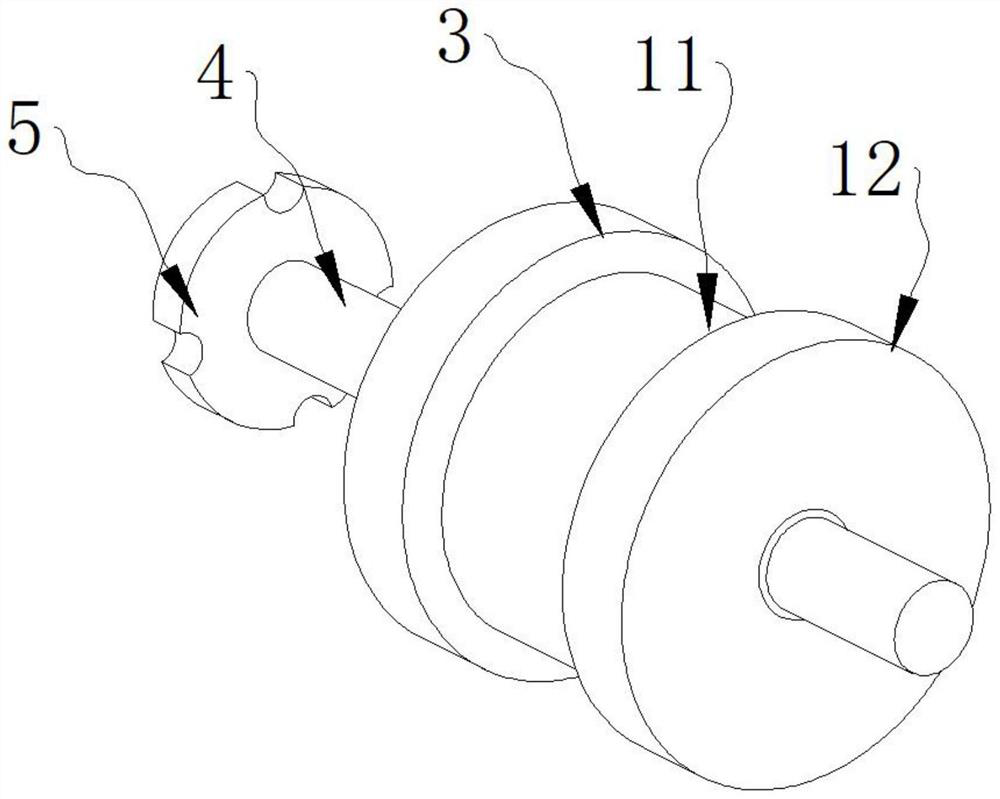
The invention provides a die-casting die spiral core-pulling mechanism which comprises a core-pulling mechanism body, the core-pulling mechanism body comprises a die, the die comprises a lower die and an upper die, a fixing base is installed between the upper die and the lower die, a movable column is installed on the fixing base, a handle is fixed to one end of the movable column, and a screw is installed on the handle. A fixing hole is formed in the top of the upper die, a fixing bolt is installed in the fixing hole, and an open hole is formed in the upper die. According to the spiral core-pulling mechanism of the die-casting die, the movable column is driven to move through the handle in the later period, the movable column drives the whole threaded column to move on the limiting ring through the supporting column, redundant waste materials are scraped through the limiting ring during displacement, burrs in the arc-shaped groove are reduced while the redundant waste materials are scraped through the limiting ring, and therefore the working quality is improved; the use is convenient.

Description

technical field [0001] The invention relates to the field of die-casting mold equipment, in particular to a spiral core-pulling mechanism of a die-casting mold. Background technique [0002] Mold is the abbreviation of a combined mold used for compression molding, extrusion molding, injection molding, blow molding and low foaming molding. Die casting mold is a large category of molds. It is a method of casting liquid forging. It is a process completed on a special die-casting die forging machine. Its basic process is: the molten metal is cast and filled into the cavity of the mold at a low or high speed. The mold has a movable cavity surface, which is cooled with the molten metal. Process pressure forging not only eliminates the shrinkage cavity and porosity defects of the blank, but also makes the internal structure of the blank reach the broken grains of the forged state. The traditional thread products with starting position requirements are all ordinary spiral core-pulli...

Claims


Application Information

Patent Timeline
IPC IPC(8): B22D17/22B22D17/20
CPCB22D17/2236B22D17/2007
Inventor 王文惠
Owner 深圳市超盛金属制品有限公司
Learn More