
Copper alloy sheet and qfn package

Active Publication Date: 2009-09-10
KOBE STEEL LTD
View PDF10 Cites 14 Cited by
  • Summary
  • Abstract
  • Description
  • Claims
  • Application Information

AI Technical Summary

Benefits of technology

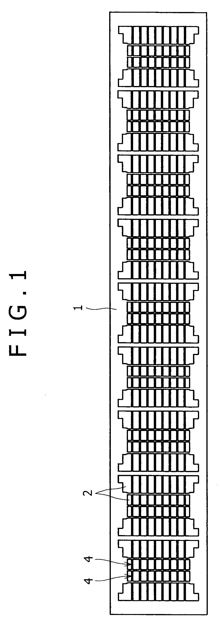
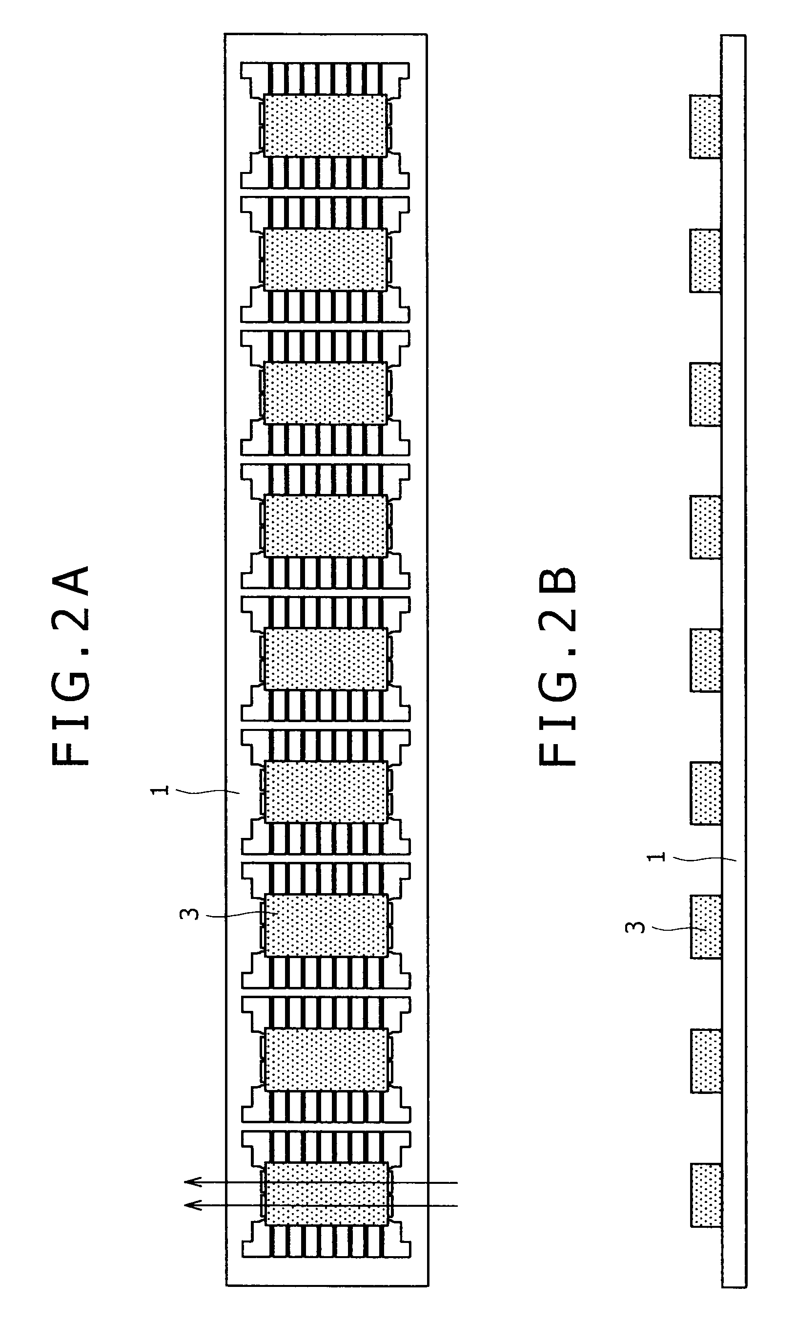
[0019]When a QFN package assembly provided with a lead frame formed by processing the copper alloy sheet of the present invention is subjected to a dicing process, burrs (lead burrs) on external leads can be reduced, the abrasion of a dicing blade employed in the dicing process can be suppressed. Consequently, the productivity of a QFN package fabricating process, the yield of QFN packages and the quality of QFN packages can be improved.

Problems solved by technology

Formation of burrs in the external leads cut by the dicing blade, which are called lead burrs, and the abrasion of the dicing blade are problems in the dicing process.
Long burrs formed on the cut leads make stable soldering for mounting packages on a substrate impossible, reduce the productivity of a mounting process and deteriorates the reliability of the packages.
The rapid abrasion of the dicing blade increases dressing frequency, and the use of a greatly worn out dicing blade produces packages of sizes different from a desired size, and reduces productivity and the yield of packages.
The alloy CDA194 is unsatisfactory in satisfactorily reducing lead burrs and in suppressing the abrasion of the dicing blade.

Method used


Image

  • Copper alloy sheet and qfn package
  • Copper alloy sheet and qfn package
  • Copper alloy sheet and qfn package

Examples


first embodiment

[0053]Examples of the first embodiment of the present invention will be described.

[0054]Copper alloys having compositions Nos. 1 to 21 shown in Table 1 and covered with charcoal were melted in the atmosphere in a small electric furnace. The molten copper alloys were cast in ingots of 50 mm in thickness, 80 mm in width and 180 mm in length. Front and back surface layers of 5 mm in thickness of each of the ingots were removed by facing. The ingots were hot-rolled at 950° C. to obtain 12 mm thick copper alloy plates. Surface layers of about 1 mm in thickness of the front and the back surface of each copper alloy plate were removed by facing. Many blow holes were formed in the ingot of the copper alloy of the composition No. 20 and cracks formed in the copper alloy plate of the copper alloy having the composition No. 21 during hot rolling. Therefore, the copper alloy plates of the compositions Nos. 20 and 21 were not processed by processes following hot rolling.

TABLE 1Chemical compositi...

second embodiment

[0076]Examples of the second embodiment of the present invention will be described.

[0077]Copper alloys having compositions Nos. 1 to 24 shown in Table 3 and covered with charcoal were melted in the atmosphere in a small electric furnace. The molten copper alloys were cast in ingots of 50 mm in thickness, 80 mm in width and 180 mm in length. Front and back surface layers of 5 mm in thickness of each of the ingots were removed by facing. The ingots were hot-rolled at 950° C. to obtain 12 mm thick copper alloy plates. Surface layers of about 1 mm in thickness of the front and the back surface of each copper alloy plate were removed by facing. Many blow holes were formed in the ingot of the copper alloy of the composition No. 23 and cracks formed in the copper alloy plate of the copper alloy having the composition No. 24 during hot rolling. Therefore, the copper alloy plates of the compositions Nos. 23 and 24 were not processed by processes following hot rolling.

TABLE 3Chemical composit...


PUM

PropertyMeasurementUnit
Fractionaaaaaaaaaa
Fractionaaaaaaaaaa
Fractionaaaaaaaaaa

Abstract

A QFN package is provided with a lead frame formed by processing a copper alloy sheet containing 0.01 to 0.50% by mass Fe, 0.01 to 0.20% by mass P, and Cu and inevitable impurities as other components, having a micro Vickers hardness of 150 or above, a uniform elongation of 5% or below and a local elongation of 10% or below, or a copper alloy sheet containing 0.05 to 2% by mass Ni, 0.001 to 0.3% by mass P, 0.005 to 5% by mass Zn, and Cu and inevitable impurities as other components, having a micro Vickers hardness of 150 or above, a uniform elongation of 5% or below and a local elongation of 10% or below. Lead burrs formed during the dicing of the QFN package are short, and a dicing blade used for dicing the QFN package is abraded at a low wear-out rate.

Description

BACKGROUND OF THE INVENTION[0001]1. Field of the Invention[0002]The present invention relates to a copper alloy sheet for forming electronic devices, such as semiconductor devices and, more particularly to a copper alloy sheet for forming QFN packages that need to be processed by dicing and a QFN package having a lead frame made from the copper alloy sheet.[0003]2. Description of the Related Art[0004]Recently, QFN packages have become prevalently used and have progressively replaced packages provided with external leads represented by QFPs and leadless packages, such as CSPs and BGAs.[0005]QFNs have become prevalently used not only because the existing QFP production lines can be used for manufacturing QFN packages, but also because QFN packages have a small area as well as BGAs and QFN packages can be formed in a small thickness comparable to that of CSPs. The QFN package having a metal lead frame can be produced at a high productivity and is superior to BGA in reliability. Since a...

Claims


Application Information

Patent Timeline
IPC IPC(8): H01L23/52C22C9/00C22C9/02C22C9/04C22C9/05C22C9/01C22C9/06
CPCC22C9/00C22C9/02C22C9/04C22C9/06H01L2924/0002H01L2924/00H01L23/50
Inventor MIWA, YOSUKENISHIMURA, MASAYASUOZAKI, RYOICHIKATSURA, SHINYA
Owner KOBE STEEL LTD
Learn More