

Magnetic head for rotary head drum
- Summary
- Abstract
- Description
- Claims
- Application Information
AI Technical Summary
Benefits of technology
Problems solved by technology
Method used
Image

Examples
first embodiment
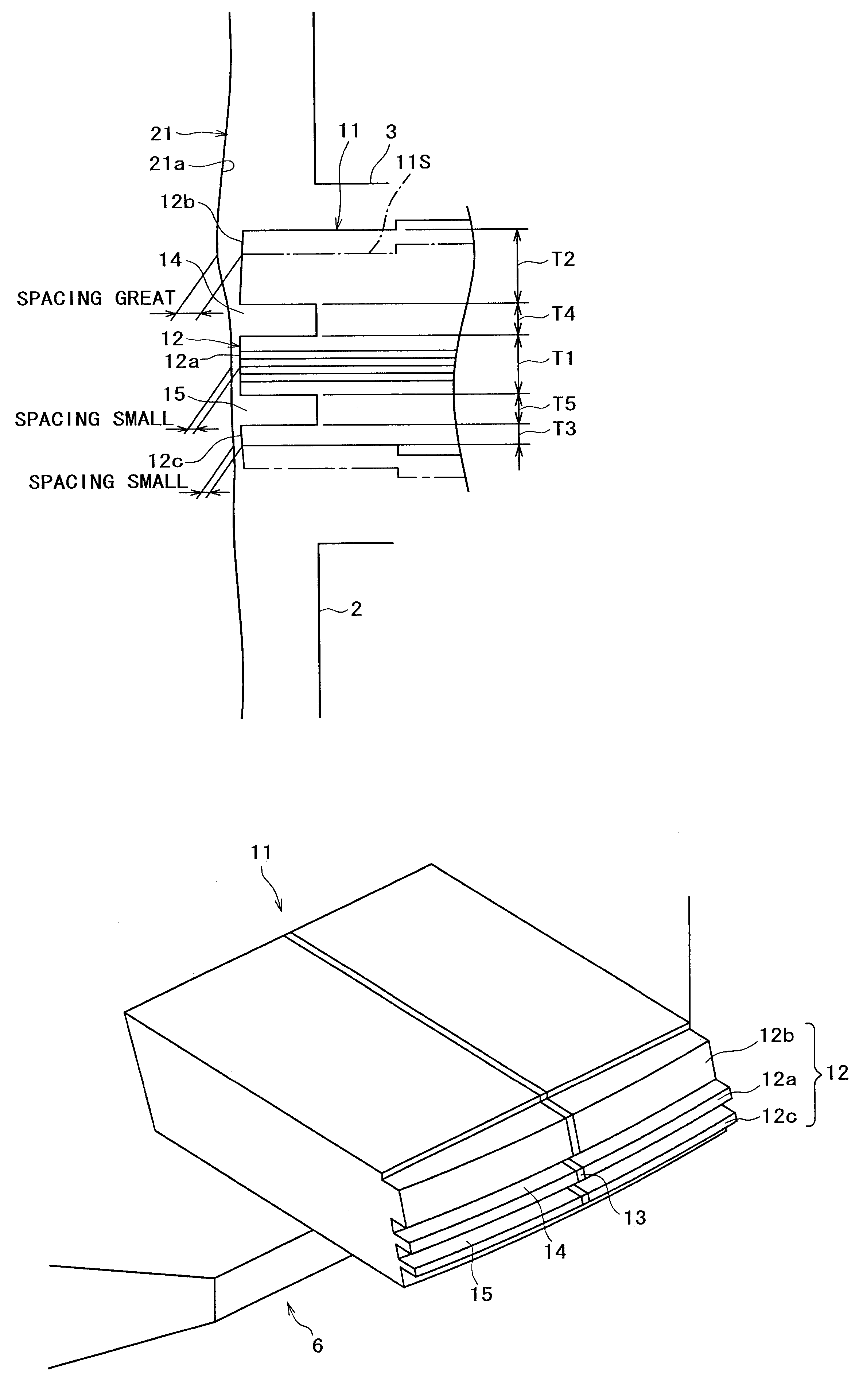
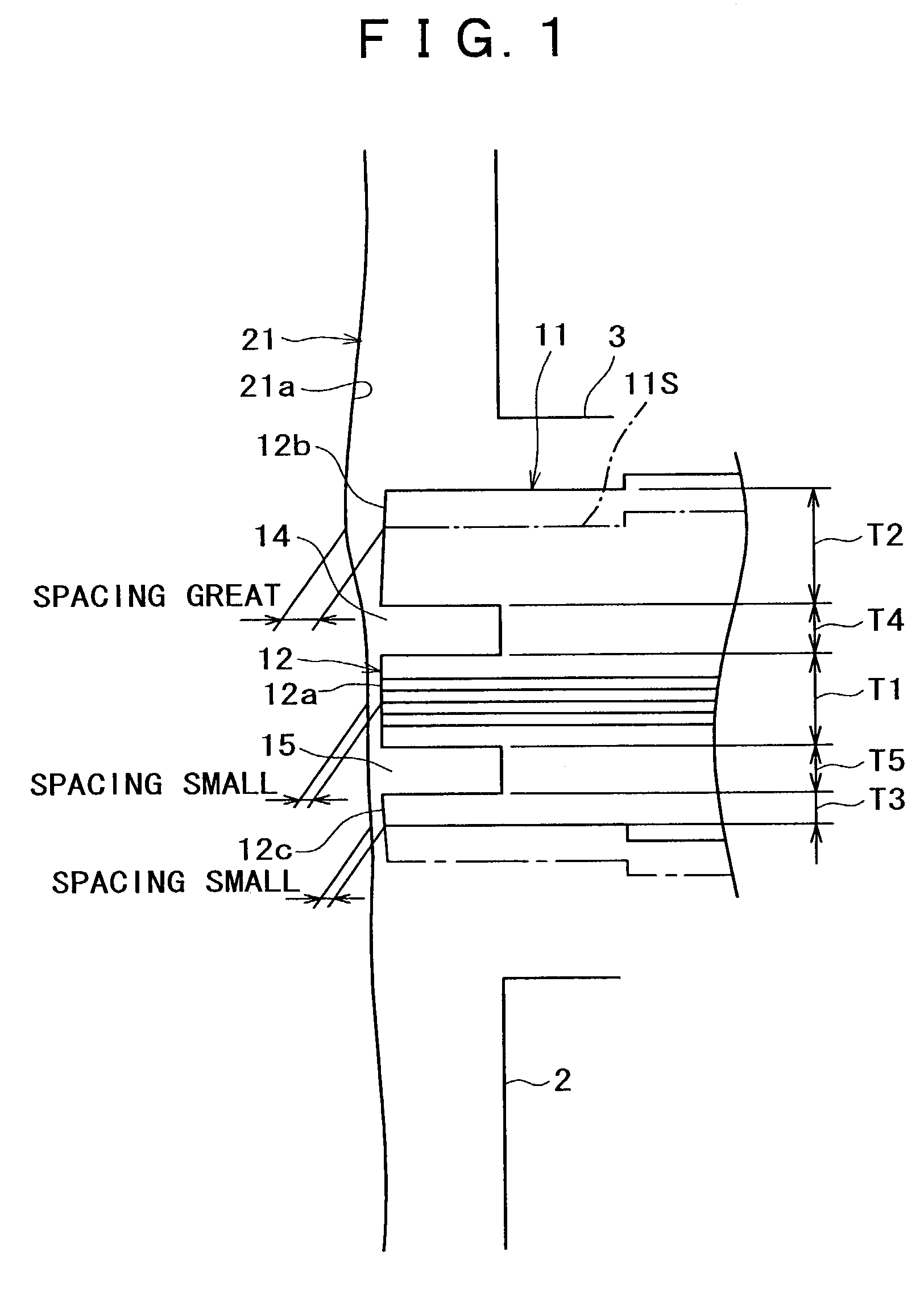
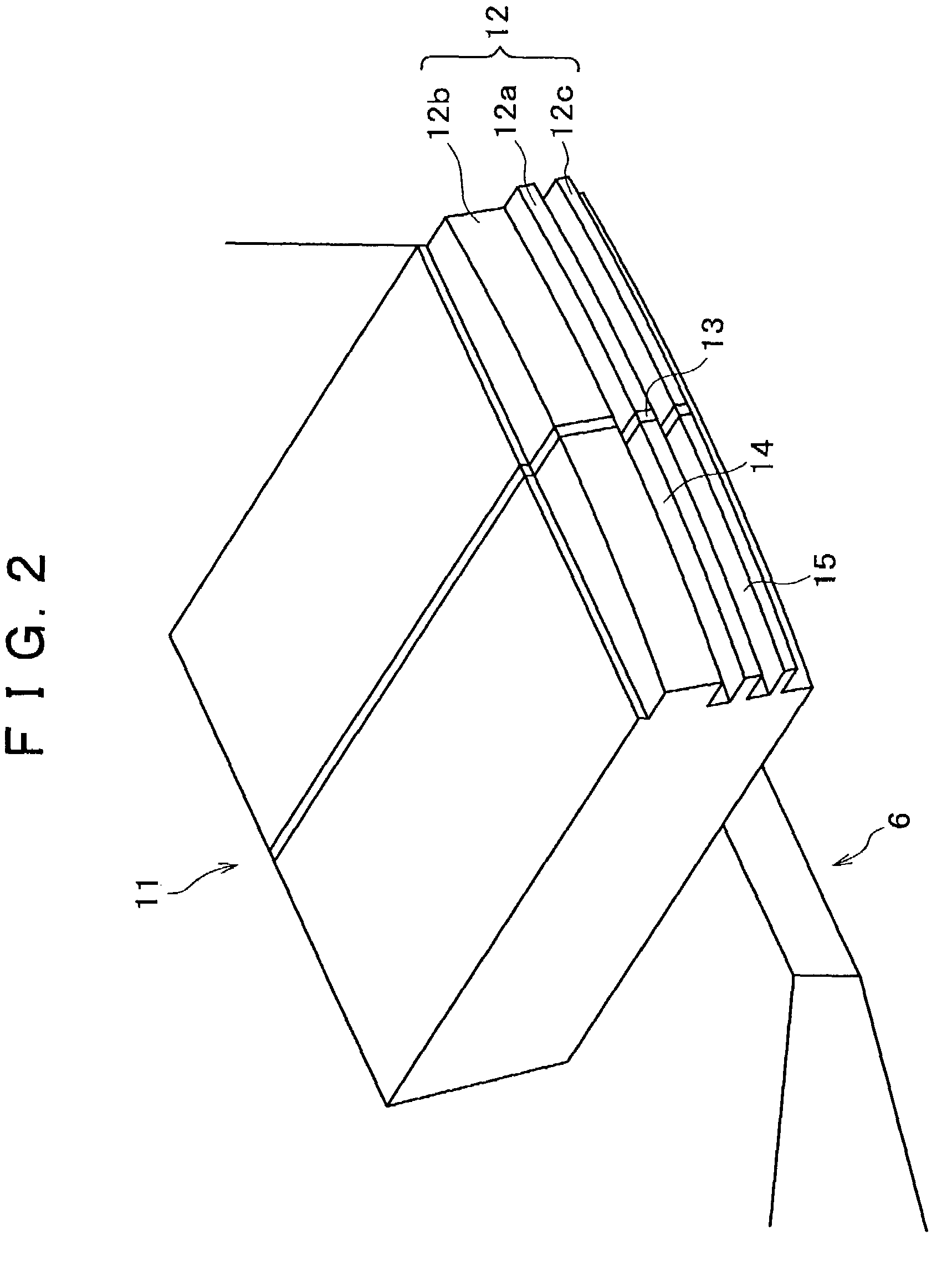
[0061]Thus, in the present first embodiment, where the thickness (vertical dimension in FIG. 1) of the central tape sliding surface 12a is represented by T1 while the thickness of the upper side tape sliding surface 12b which contacts with the magnetic tape 21 earlier than the central tape sliding surface 12a is represented by T2 and the thickness of the lower side tape sliding surface 12c which contacts with the magnetic tape 21 later than the central tape sliding surface 12a is represented by T3, the tape sliding surface 12 is formed so as to satisfy a relationship in thickness of T2>T1≧T3. It is to be noted that, where the thickness of the upper side groove 14 is represented by T4 and the thickness of the lower side groove 15 is represented by T5, the tape sliding surface 12 is formed so as to satisfy a relationship in thickness of T4=T5.
[0062]It is to be noted that the dimensions may be, for example, T1=approximately 73 μm, T2=approximately 150 to 200 μm, T3=approximately 54 μm,...
fourth embodiment
[0074]Referring now to FIGS. 7 to 9, there is shown a still further magnetic head for a rotary head drum to which the present invention is applied. A head chip 11 of the magnetic head according to the present fourth embodiment is configured such that a pair of upper and lower grooves 14 and 15 for allowing air to escape therethrough are formed in parallel to each other on the opposite upper and lower sides of a magnetic gap 13 formed at a substantially center of a tape sliding surface 12 of the head chip 11 but in an inclined relationship by an angle of elevation of a predetermined inclination angle θ with respect to a rotatory direction A of the head chip 11.
[0075]Where the sliding width of the magnetic gap 13 on the magnetic tape 21 is w while the length of the tape sliding surface 12 is L and the length of the pair of grooves 14 and 15 is L, the grooves 14 and 15 are preferably formed such that they satisfy
θ≧w / (L / 2) (1)
The inclination angle θ is preferably within 10° and most pr...
fifth embodiment
[0083]Referring now to FIG. 11, there is shown a yet further rotating magnetic head for a rotary head drum to which the present invention is applied. A head chip 11 of the rotating magnetic head according to the present fifth embodiment is generally configured such that a pair of upper and lower parallel grooves 14 and 15 are inclined at a depression angle of a predetermined angle θ with respect to a rotatory direction A of the head chip 11.
[0084]With the head chip 11 shown in FIG. 11, a foreign substance 31 such as a magnetic particle transferred from the magnetic tape 21 to the tape sliding surface 12 between the pair of upper and lower grooves 14 and 15 on the leading side in the rotatory direction A of the magnetic gap 13 is admitted into the lower side groove 15 intermediately while it is carried in the opposite rotatory direction B toward the magnetic gap 13 side on the tape sliding surface 12 as the head chip 11 rotates in the rotatory direction A. Consequently, the foreign s...
PUM
 Abstract
Description
Claims
Application Information