Divided cage and joint member for wind power generation apparatus

Inactive Publication Date: 2016-11-17
JTEKT CORP
View PDF0 Cites 0 Cited by
  • Summary
  • Abstract
  • Description
  • Claims
  • Application Information

AI Technical Summary

Benefits of technology

[0022]With the divided cage according to an aspect of the present invention, the abrasion on the side faces of both the ring-shaped portions thereof opposing each other in the axial direction can be suppressed. Furthermore, with the joint member for the power generation apparatus

Problems solved by technology

This kind of wind power generation apparatus has a problem that power generation efficiency lowers because the rotation speed transmitted from the blade to the generator via the main spindle, speed increaser, etc. is changed by the change in wind speed and wind direction.
However, since the pocket 108 is formed in the space enclosed with the ring-shaped portions 106 and the pillar portions 107, and since the pillar portion 107 has the protruding portion 109 and is formed into a complicated shape,

Method used


Image

  • Divided cage and joint member for wind power generation apparatus
  • Divided cage and joint member for wind power generation apparatus
  • Divided cage and joint member for wind power generation apparatus

Examples


Example

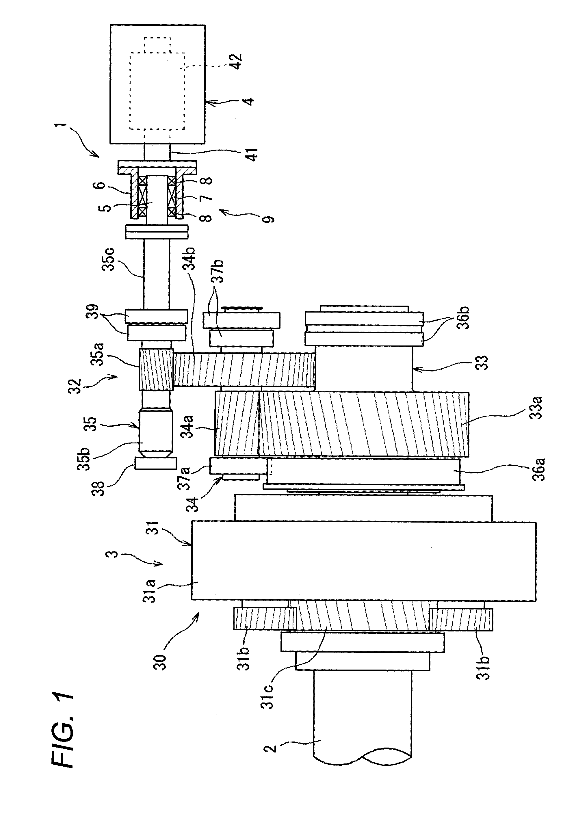
[0033]FIG. 1 is a schematic view showing the configuration of a power generation apparatus. This power generation apparatus is a wind power generation apparatus 1 and is equipped with a main spindle 2 that is rotated by receiving wind power (external force), a speed increaser 3 connected to this main spindle 2, and a generator 4 connected to this speed increaser 3, wherein the rotation of the main spindle 2 is increased by the speed increaser 3 and the generator 4 is driven by the increased rotation of the shaft, thereby generating electric power.

[0034]The generator 4 is configured, for example, using an induction generator, and has an input shaft 41 to which the rotation increased by the speed increaser 3 is input so that the input shaft 41 is rotated, a rotor 42 incorporated in the generator 4, a stator, not shown, etc. The rotor 42 is connected to the input shaft 41 so as to be rotatable integrally therewith, and the generator 4 is configured so that the input shaft 41 rotates to...


PUM


Abstract

In a divided cage, a plurality of pockets for accommodating engaging elements between an inner ring and an outer ring of a one-way clutch are formed in a circumferential direction. The divided cage includes: a pair of ring-shaped portions which oppose each other in an axial direction and which are provided between the inner ring and the outer ring; and a plurality of pillar portions which are separated members from the pair of ring-shaped portions and which have end portions in the axial direction connected to the ring-shaped portions. Side faces of both the ring-shaped portions opposing each other in the axial direction are subjected to abrasion resistance treatment.

Description

TECHNICAL FIELD[0001]An aspect of the present invention relates to a divided cage for use in a one-way clutch and to a joint member for a wind power generation apparatus equipped with the divided cage.BACKGROUND ART[0002]As a wind power generation apparatus, an apparatus is known in which a blade receives wind power, a main spindle connected to the blade is rotated, and the rotation of the main spindle is increased by a speed increaser to drive a generator. This kind of wind power generation apparatus has a problem that power generation efficiency lowers because the rotation speed transmitted from the blade to the generator via the main spindle, speed increaser, etc. is changed by the change in wind speed and wind direction.[0003]Hence, the applicants of this application have already proposed a wind power generation apparatus in which a one-way clutch is disposed between the speed increaser and the generator to improve power generation efficiency (refer to Patent Document 1). In thi...

Claims


Application Information

Patent Timeline
IPC IPC(8): F03D15/00F03D80/70F16D41/067F03D9/00
CPCF03D15/00F03D9/002F16D2041/0605F16D41/067F03D80/70F16D2041/0608F03D9/25Y02E10/72
Inventor FUJIWARA, HIDEKI
Owner JTEKT CORP
Why Eureka
Try Eureka