Friction Transmission Belt

Inactive Publication Date: 2019-05-02
MITSUBOSHI BELTING LTD
View PDF0 Cites 1 Cited by
  • Summary
  • Abstract
  • Description
  • Claims
  • Application Information

AI Technical Summary

Benefits of technology

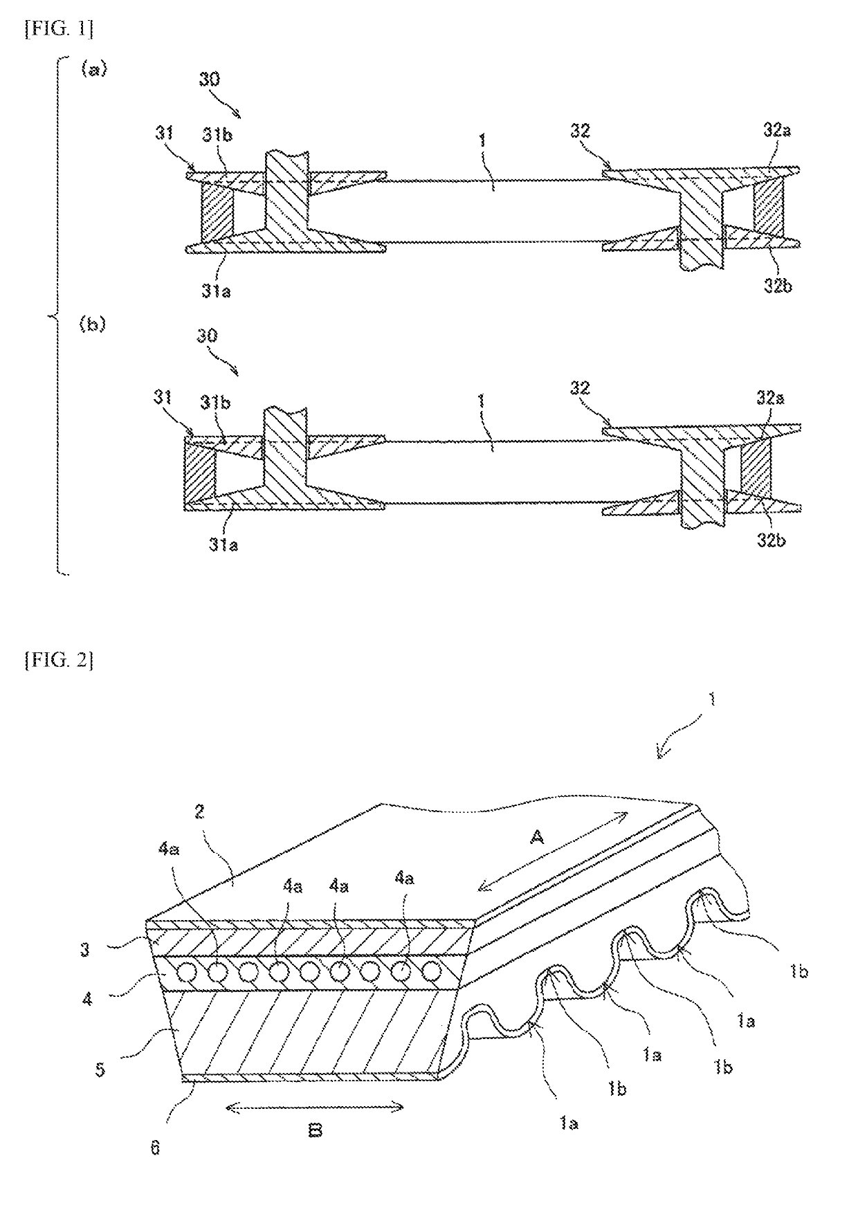
[0028]In the present invention, the adhesion rubber layer of the frictional power transmission belt is formed of a vulcanized rubber composition containing a rubber component and carbon black in a predetermined proportion and not substantially containing silica, and a surface of the tension member is covered with an overcoat layer formed of another vulcanized rubber composition containing a rubber component and silica. Therefore, the adhesion rubber layer is specialized for stress dispersion function due to high mechanical characteristics

Problems solved by technology

On the other hand, if the mechanical characteristic of the adhesion rubber layer is excessively increased, a bending fatigue resistance decreases.
However, from a viewpoint of compounding design of such a rubber composition, the following problems (1) to (4) which are caused by running of the belt in a high-load environment and may pose a decrease in durability (lifetime) are concerned.
(1) Low adhesiveness between a cord and an adhesion rubber layer leads to peeling between the cord and the adhesion rubber layer.
(2) A high friction coefficient of a contact surface (power transmission surface) of the belt with respect to a pulley easily leads to a deformation of the belt (in particular, buckling called dishing) since the belt does not smoothly move.
In particular, the shear stress is likely to concentrate on the interfaces having a difference in mechanical characteristics (in this case, interface between compression rubber layer or tension rubber layer and adhesion rubber layer), which leads to an interfacial peeling (cracks).
However, with these methods of blending silica as a reinforcing material, although adhesiveness is enhanced, it is disadvantageous in mechanical characteristics such as interfacial peeling resistance, abrasion resistance

Method used


Image

  • Friction Transmission Belt
  • Friction Transmission Belt

Examples


Example

EXAMPLE

[0111]Hereinafter, the present invention will be described in more detail based on Examples, but the present invention is not limited to these Examples. In the following

[0112]Examples, the raw materials used in Examples, the measurement methods or evaluation methods for each physical property are illustrated below. Unless otherwise specified, “parts” and “%” are on a mass basis.

[Raw Material]

[0113]Chloroprene rubber: “R22” manufactured by Tosoh Corporation

[0114]Carbon black: “Seast 3” manufactured by Tokai Carbon Co., Ltd.

[0115]Silica: “Ultrasil VN-3” manufactured by Evonik Degussa Japan Ltd., specific surface area of from 155 to 195 m2 / g

[0116]Naphthene oil: “NS-900” manufactured by Idemitsu Kosan Co., Ltd.

[0117]Resorcin-formalin copolymer (resorcinol resin): Resorcinol-formalin copolymer having less than 20% of resorcinol and less than 0.1% of formalin

[0118]Antioxidant: “Nonflex OD3” manufactured by Seiko Chemical Industry Co., Ltd.

[0119]Vulcanization accelerator TMTD: tetra...

Example

Examples 1 to 6 and Comparative Examples 1 to 4

(Formation of Rubber Layer)

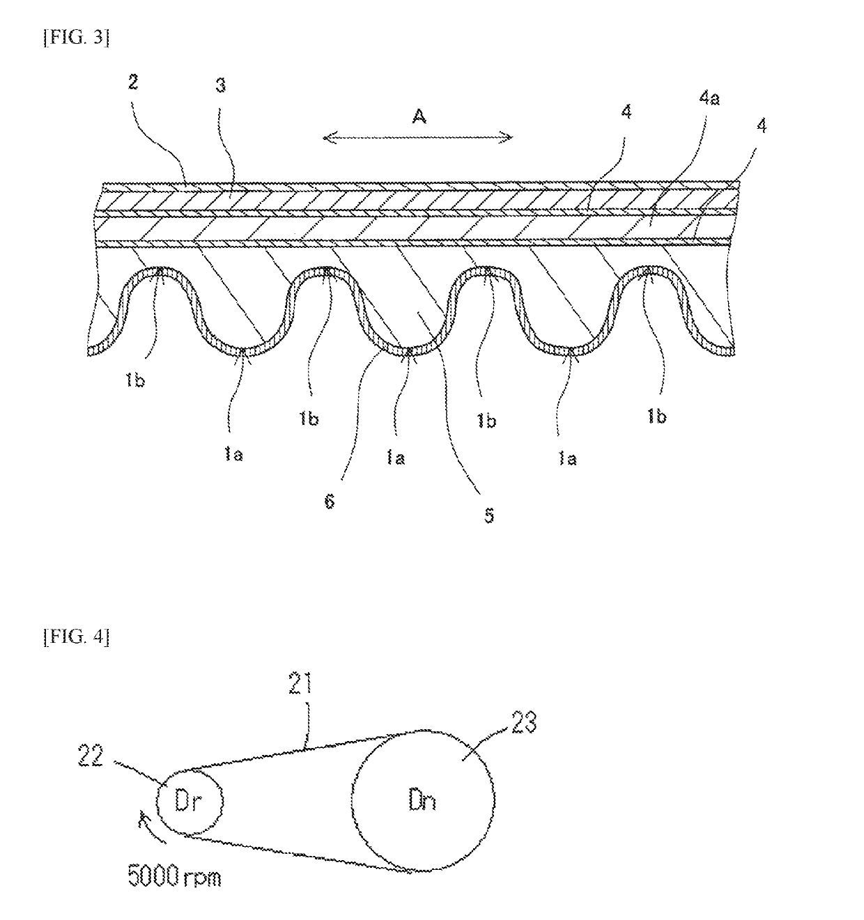
[0138]Each of the rubber compositions of Table 1 (adhesion rubber layer) and Table 2 (compression rubber layer and tension rubber layer) was subjected to rubber kneading by using a known method such as a Banbury mixer and the kneaded rubber was passed through a calendar roll to prepare a rolled rubber sheet (adhesion rubber layer sheet, compression rubber layer sheet, and tension rubber layer sheet). In addition, for the rubber composition used for the adhesion rubber layer, the physical properties of the vulcanized rubber are shown in Table 1.

TABLE 1(Adhesion rubber layer)XYZVWUComposi-Chloroprene100tionrubber(parts)Carbon black605040307020Silica01020000Naphthene oil5Magnesium oxide4Resorcin-formalin1copolymerAntioxidant4Zinc oxide5Vulcanization1acceleratorTMTDN,N′-m-2phenylene di-maleimideStearic acid2Hexamethoxy-3methylolmelaminePhysicalHardness (°)838485788575propertiesAbrasion amount140155170200135260of v...

Example

[0148]Comparative Example 1 was a frictional power transmission belt containing 20 parts by mass of silica in the adhesion rubber layer, and the amount of abrasion of the belt during 24 hours running was large, and abrasion of the pulley was also observed. Comparative Example 2 was a frictional power transmission belt not containing silica in any of the adhesion rubber layer and the overcoat layer (coating film), and the cord was peeled off at the side of the belt after running for 24 hours (degree of causing practical problem). Comparative Example 3 was a frictional power transmission belt containing 10 parts by mass of silica in the adhesion rubber layer and not containing silica in the overcoat layer (coating film), and the cord peeled off at the side of the belt after running for 24 hours (degree of causing practical problem). Comparative Example 4 was a frictional power transmission belt in which the amount of carbon black in the adhesion rubber layer was as small as 20 parts b...


PUM

PropertyMeasurementUnit
Percent by massaaaaaaaaaa
Thicknessaaaaaaaaaa

Abstract

Provided is a frictional power transmission belt containing an adhesion rubber layer in contact with at least a portion of a tension member extending in a longitudinal direction of the belt, in which the adhesion rubber layer is formed of a first vulcanized rubber composition containing a rubber component and a filler. The filler contains substantially no silica and contains 30 parts by mass or more of carbon black based on 100 parts by mass of the rubber component, and the tension member has, on a surface thereof, an overcoat layer formed of a second vulcanized rubber composition containing a rubber component and silica.

Description

TECHNICAL FIELD[0001]The present invention relates to a frictional power transmission belt in which a frictional power transmission surface is formed to be inclined in a V shape, such as a V-belt and a V-ribbed belt, and in more detail, it relates to a frictional power transmission belt that is excellent in mechanical characteristics such as interfacial peeling resistance, abrasion resistance and low friction coefficient.BACKGROUND ART[0002]Conventionally, a frictional power transmission belt such as a V-belt, a V-ribbed belt and a flat belt has been known as a power transmission belt that transmits power. The V-belt or V-ribbed belt in which a frictional power transmission surface (V-shaped side surface) is formed of a V-angle is wound with tension applied between a drive pulley and a driven pulley, and rotates between two axes in a state where the V-shaped side surface is in contact with V-grooves of the pulleys. In the process, power is transmitted by utilizing an energy accompan...

Claims


Application Information

Patent Timeline
IPC IPC(8): F16G5/08F16G5/20B29D29/10B32B3/26B32B25/10B32B25/02
CPCF16G5/08F16G5/20B29D29/106B32B3/263B32B25/10B32B25/02B32B2433/04B29K2509/02B29K2507/04F16G1/08F16G5/06F16G1/10
Inventor ISHIGURO, HISATOTOMODA, TAKUYA
Owner MITSUBOSHI BELTING LTD
Why Eureka
Try Eureka