
Contact seat for electric switch machine

A technology of contact seat and switch machine, which is applied in the direction of contact drive mechanism, electrical equipment for manipulating turnout or line breaker, railway signal, etc. It can solve the problem of delaying normal driving, moving contact group jamming, indicating circuit, switching Large resistance and other problems to achieve the effect of preventing protruding, ensuring smoothness, and improving conversion power

Pending Publication Date: 2020-09-01
TIANJIN RAILWAY SIGNAL
View PDF0 Cites 1 Cited by
  • Summary
  • Abstract
  • Description
  • Claims
  • Application Information

AI Technical Summary

Problems solved by technology

As an important part in the switch machine, the contact block realizes the switching function of the action and the display circuit, and feeds back the signal to the interlock system. However, due to the long-term friction between its own moving contact group and static contact group, there will be excessive switching resistance. In this case, after the turnout is switched in place, the blockage of the moving contact group cannot be switched and connected normally, which means that the circuit is faulty and the normal driving is delayed.

Method used


Image

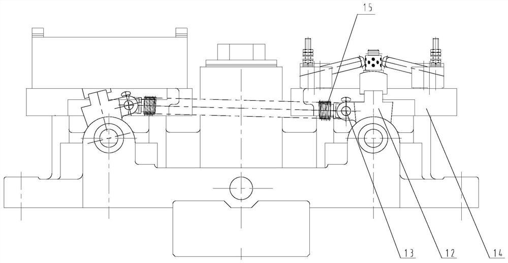
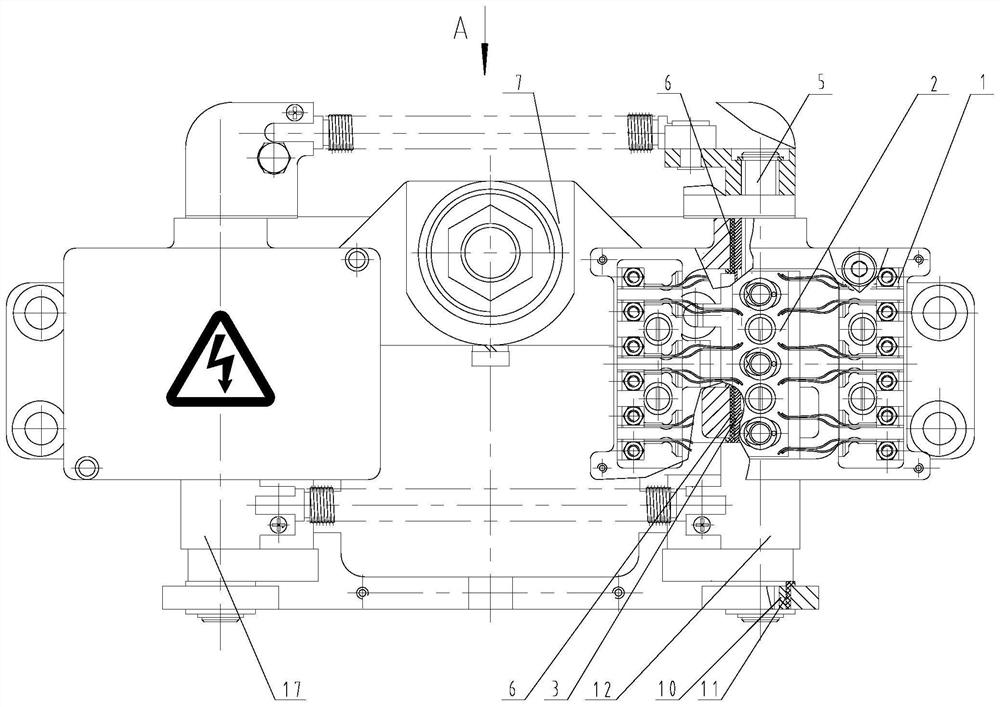
  • Contact seat for electric switch machine
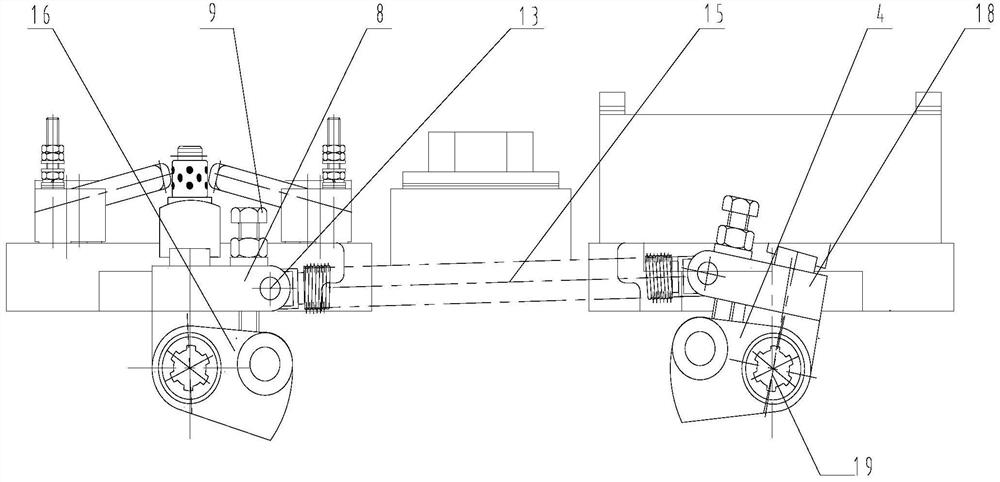
  • Contact seat for electric switch machine
  • Contact seat for electric switch machine

Examples


Embodiment Construction

[0044] It should be noted that, in the case of no conflict, the embodiments of the present invention and the features in the embodiments can be combined with each other.

[0045] In describing the present invention, it should be understood that the terms "center", "longitudinal", "transverse", "upper", "lower", "front", "rear", "left", "right", " The orientations or positional relationships indicated by "vertical", "horizontal", "top", "bottom", "inner" and "outer" are based on the orientations or positional relationships shown in the drawings, and are only for the convenience of describing the present invention and Simplified descriptions, rather than indicating or implying that the device or element referred to must have a particular orientation, be constructed and operate in a particular orientation, and thus should not be construed as limiting the invention. In addition, the terms "first", "second", etc. are used for descriptive purposes only, and should not be understood ...


PUM


Abstract

The invention provides a contact seat for an electric switch machine. The contact seat comprises a contact seat base body, fixing plates used for assembling a static contact set and a support used forassembling a movable contact set. The support comprises a left support and a right support which are symmetrically connected to the contact seat base body through movable contact shafts respectively;a tension spring is arranged between the left support and the right support; fixing plates corresponding to the positions of the left support are arranged on the two sides of the left support respectively; fixing plates corresponding to the positions of the right support are respectively arranged on two sides of the right support; one end of the movable contact shaft is provided with an adjustingplate capable of rotating relative to the contact seat base body; and a tension spring is arranged between the right adjusting plate and the left adjusting plate. According to the contact seat for the electric switch machine, the tension spring between the left adjusting plate and the right adjusting plate and the tension spring between the left support and the right support form a double-tension-spring system, conversion power of the movable contact set is improved, and conversion stability of the movable contact set is improved.

Description

technical field [0001] The invention belongs to the technical field of railway switch switching equipment, in particular to a contact seat for an electric switch machine. Background technique [0002] The function of the electric switch machine is to switch and lock the switch rail / core rail, change the opening direction of the switch, and reflect the position status of the switch rail / core rail through the contacts. As an important part in the switch machine, the contact block realizes the switching function of the action and the display circuit, and feeds back the signal to the interlock system. However, due to the long-term friction between its own moving contact group and static contact group, there will be excessive switching resistance. In this case, after the turnout is switched in place, the blockage of the moving contact group cannot be switched and connected normally, indicating a circuit failure and delaying normal driving. Contents of the invention [0003] In...

Claims


Application Information

Patent Timeline
Patent Type & Authority Applications(China)
IPC IPC(8): B61L5/06H01H3/38H01H3/32
CPCB61L5/06H01H3/38H01H3/32
Inventor 刘畅王志文朴盛斌张振李倩文李斌郭金贵李旺龙
Owner TIANJIN RAILWAY SIGNAL
Learn More