
Lifting system

A lifting system and lifting rod technology, applied in the field of lifting rods, can solve problems such as affecting the normal operation of top equipment and interlacing cables

Pending Publication Date: 2020-09-01
中国人民解放军第六九〇五工厂
View PDF0 Cites 0 Cited by
  • Summary
  • Abstract
  • Description
  • Claims
  • Application Information

AI Technical Summary

Problems solved by technology

When the lifting rod is raised and lowered, the cables may not be automatically retracted and retracted, which may cause the cables to be intertwined and affect the normal operation of the top equipment

Method used


Image

  • Lifting system
  • Lifting system
  • Lifting system

Examples


Embodiment Construction

[0044] Embodiments of the present invention are described in detail below, examples of which are shown in the drawings, wherein the same or similar reference numerals designate the same or similar elements or elements having the same or similar functions throughout. The embodiments described below by referring to the figures are exemplary and are intended to explain the present invention and should not be construed as limiting the present invention.

[0045] In describing the present invention, it should be understood that the terms "length", "width", "upper", "lower", "front", "rear", "left", "right", "vertical", The orientation or positional relationship indicated by "horizontal", "top", "bottom", "inner", "outer", etc. are based on the orientation or positional relationship shown in the drawings, and are only for the convenience of describing the present invention and simplifying the description, rather than Nothing indicating or implying that a referenced device or element...


PUM


Abstract

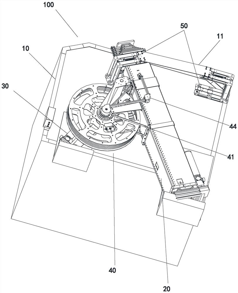
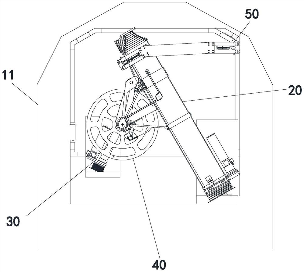
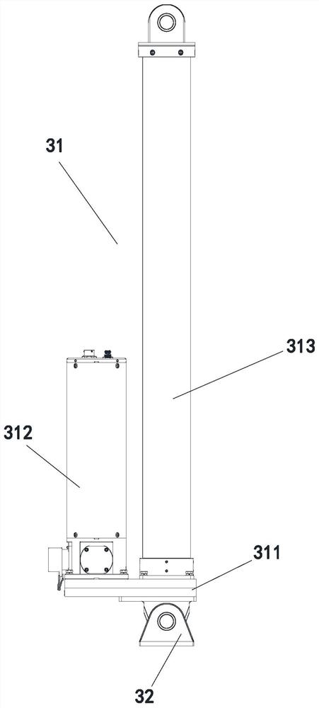
The invention discloses a lifting system. A tube assembly pushes a lifting rod so that the lifting rod deflects; during the deflection process, the lifting rod is slowly clamped into a clamp body until the lifting rod is in contact with a clip, the clip rotates around a rotating pin, so that the other surface of the clip is in contact with the lifting rod, so that the lifting rod is clamped, and the fixed state of the lifting rod is maintained; when the lifting rod is stretched, a lifting rod tube close to working equipment provides power to pull a cable out of a take-up and pay-off wheel; when the take-up and pay-off wheel rotates, a drum is driven to take up a steel wire rope, so as to realize the recovery of the steel wire rope outside the lifting rod; and when the lifting rod is contracted, the steel wire rope provides a pulling force, so that the take-up and pay-off wheel rotates and the cable is recovered, so that the lifting system integrates the functions of automatic take-up,falling, and in-place locking.

Description

technical field [0001] The invention relates to the technical field of lifting rods, in particular to a lifting system. Background technique [0002] At present, most of the lifting rods have the disadvantages that the position is fixed after assembly, and the rod body of the lifting rod cannot be deflected. When the lifting mast is loaded into the vehicle and encounters tunnels, height-limited buildings, height-limited mountains, etc., due to the disadvantage that the pole body cannot be deflected, this will limit the passing height during transportation. Most lifting poles have no specific fastening device after loading, and the vibration caused by different road conditions during transportation will reduce the stability of the equipment. In addition, large-scale equipment is installed on the top of the lifting rod, and there are very long cables on the equipment. When the lifting pole is raised and lowered, the cables may not be retracted automatically, which may cause ...

Claims


Application Information

Patent Timeline
Patent Type & Authority Applications(China)
IPC IPC(8): B65H75/38B65H75/44
CPCB65H75/38B65H75/4402
Inventor 姜渝江国辉段海军冉景扬钟维华
Owner 中国人民解放军第六九〇五工厂
Learn More