An Atmospheric Pressure Filling Machine Capable of Preventing Dripping and Sucking Back

A filling machine and anti-drip technology, used in liquid bottling, pressure-free perfusion, packaging, etc., can solve problems such as sucking back, and achieve the effect of preventing retention

Active Publication Date: 2022-01-11
南京硕华机械设备有限公司
View PDF0 Cites 2 Cited by
  • Summary
  • Abstract
  • Description
  • Claims
  • Application Information

AI Technical Summary

Problems solved by technology

[0003] After the existing normal pressure filling machine stops filling, because there is no liquid in the filling tube to continue to output, there is a section of empty tube, and at this time, there is still some liquid left in the port of the filling tube. Into the filling bottle, so that the air pressure inside the filling tube is lower than the air pressure outside the tube, so that the liquid at the port flows inward, forming a suction phenomenon

Method used


Image

  • An Atmospheric Pressure Filling Machine Capable of Preventing Dripping and Sucking Back
  • An Atmospheric Pressure Filling Machine Capable of Preventing Dripping and Sucking Back
  • An Atmospheric Pressure Filling Machine Capable of Preventing Dripping and Sucking Back

Examples


Embodiment 1

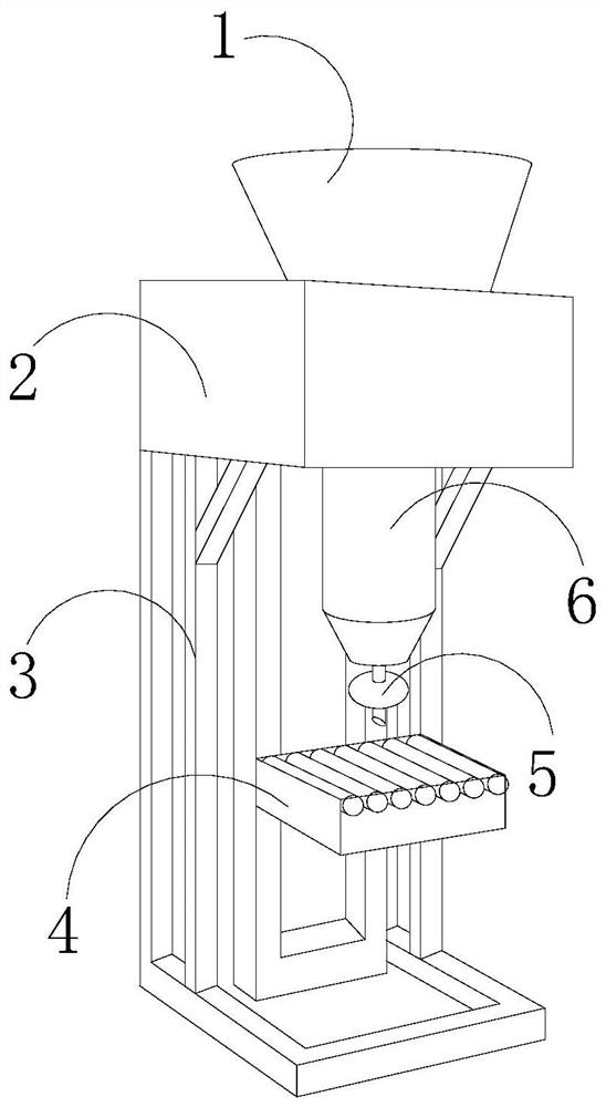
[0028] see Figure 1-Figure 7 , the present invention provides an atmospheric pressure filling machine capable of preventing dripping and sucking back, the structure of which includes a feed hopper 1, a fixed seat 2, a fixed frame 3, a workbench 4, a filling head 5, and a connecting cavity 6. The feed hopper 1 is installed on the fixed seat 2, the feed hopper 1 communicates with the connecting chamber 6, and the bottom of the connecting chamber 6 is provided with a filling head 5, and the filling head 5 is arranged in the north direction of the working table 4 , the filling head 5 is matched with the workbench 4, the fixed frame 3 is mechanically welded with the fixed seat 2, and the fixed frame 3 is fixedly connected with the workbench 4;

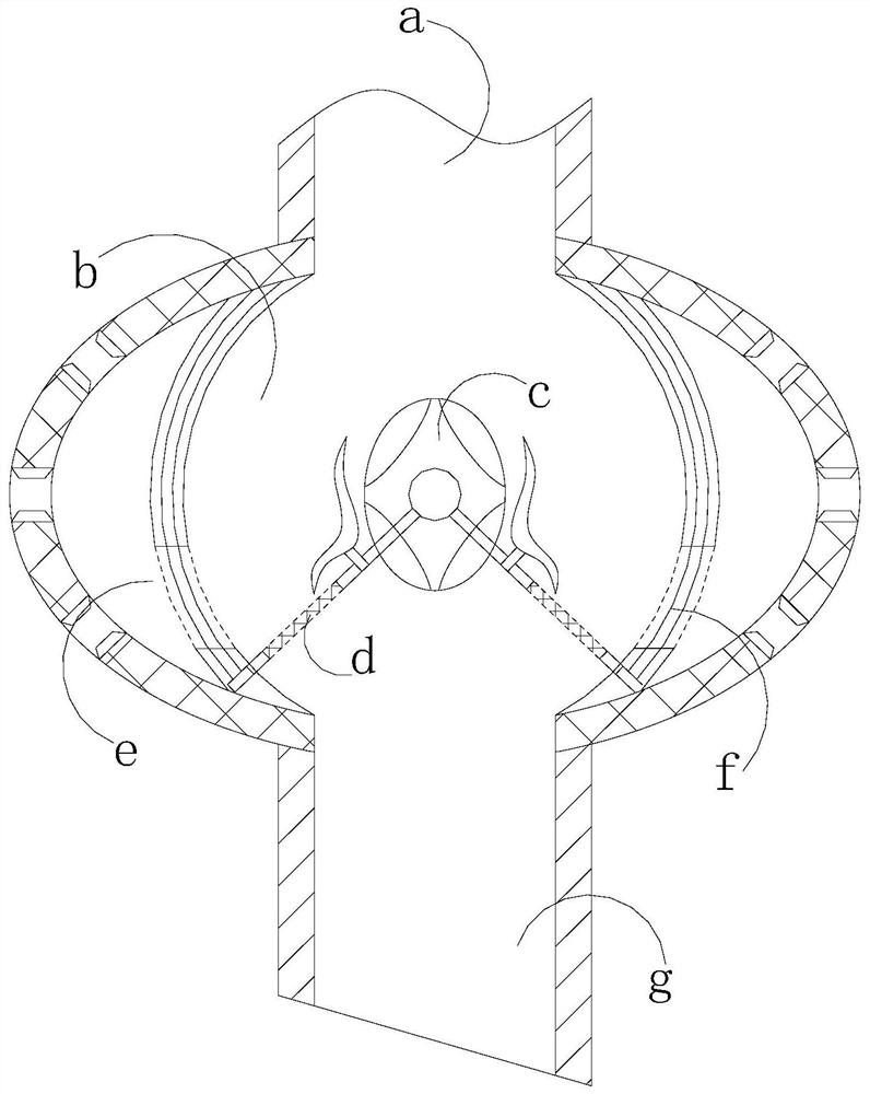
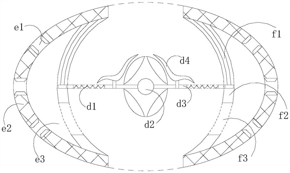
[0029] The filling head 5 is composed of a communication pipe a, a middle chamber b, a fixed block c, a movable plate d, an air pressure balance ring f, a balance ball e, and a filling pipe g. The communication pipe a communicates with the...

Embodiment 2

[0039] see Figure 1-Figure 2 , Figure 4 , Image 6 , the present invention provides an atmospheric pressure filling machine capable of preventing dripping and sucking back, the structure of which includes a feed hopper 1, a fixed seat 2, a fixed frame 3, a workbench 4, a filling head 5, and a connecting cavity 6. The feed hopper 1 is installed on the fixed seat 2, the feed hopper 1 communicates with the connecting chamber 6, and the bottom of the connecting chamber 6 is provided with a filling head 5, and the filling head 5 is arranged in the north direction of the working table 4 , the filling head 5 is matched with the worktable 4, the fixed frame 3 is mechanically welded with the fixed seat 2, and the fixed frame 3 is fixedly connected with the worktable 4; the filling head 5 is composed of the communication pipe a, the middle Cavity b, fixed block c, movable plate d, air pressure balance ring f, balance ball e, and filling pipe g. The fixed block c is connected with t...


PUM


Abstract

The invention discloses a normal-pressure filling machine capable of preventing dripping and sucking back. Its structure includes a feeding hopper, a fixed seat, a fixed frame, a workbench, a filling head, and a connecting cavity. The feeding hopper is installed on the fixed seat. , the feeding hopper communicates with the connecting chamber, the bottom of the connecting chamber is equipped with a filling head, the filling head is set in the north direction of the workbench, the filling head is matched with the workbench, the fixing frame and the fixing seat are mechanically welded, and the fixing frame and the working table are mechanically welded. The table is fixedly connected, and the beneficial effect of the present invention is that by setting up a drainage block in the middle cavity, the liquid reaching the drainage block can be guided under the action of the guide plate and the guide block, so as to prevent the retention of the filling liquid. When rotating around the central axis, it drives the telescopic plate to move accordingly to realize the opening and closing control of the vent. With the help of the vent, when the filling is stopped, the air pressure balance between the middle cavity and the outside world can be achieved, thereby preventing the filling tube from leaking. The air pressure is less than the air pressure outside the tube, causing the liquid to flow back and suck back.

Description

technical field [0001] The invention relates to the field of filling machines, in particular to an atmospheric filling machine capable of preventing dripping and sucking back. Background technique [0002] The liquid is independently powdered in the bottle and sold after sealing it, while the traditional packaging method is to insert the conical funnel into the bottle mouth to guide the liquid into the bottle. Loading machine, the current normal pressure filling machine has the following defects: [0003] After the existing normal pressure filling machine stops filling, because there is no liquid in the filling tube to continue to output, there is a section of empty tube, and at this time, there is still some liquid left in the port of the filling tube. Into the filling bottle, so that the air pressure inside the filling tube is lower than the air pressure outside the tube, so that the liquid at the port flows inward, forming a suck-back phenomenon. Contents of the invent...

Claims


Application Information

Patent Timeline
Patent Type & Authority Patents(China)
IPC IPC(8): B67C3/26B67C3/24B67C3/04
CPCB67C3/26B67C3/24B67C3/04
Inventor 陈华
Owner 南京硕华机械设备有限公司
Why Eureka
Try Eureka