A kind of sole release agent spraying equipment

A technology of spraying equipment and release agent, which is applied to other household appliances, household appliances, household components, etc., can solve the problems of easy mixing of release agents, time-consuming and labor-intensive, etc., and achieve the effect of ensuring accurate interception

Active Publication Date: 2021-11-09
江西正博实业有限公司
View PDF11 Cites 0 Cited by
  • Summary
  • Abstract
  • Description
  • Claims
  • Application Information

AI Technical Summary

Problems solved by technology

[0004] In order to overcome the disadvantages of manual operation, time-consuming and labor-consuming, and easy confusion of release agents, the technical problem of the present invention is to provide a method that can replace manual work and automatically spray different release agents on the upper and lower molds. Sole release agent spraying equipment that will not spray the release agent in the wrong position

Method used


Image

  • A kind of sole release agent spraying equipment
  • A kind of sole release agent spraying equipment
  • A kind of sole release agent spraying equipment

Examples


Embodiment 1

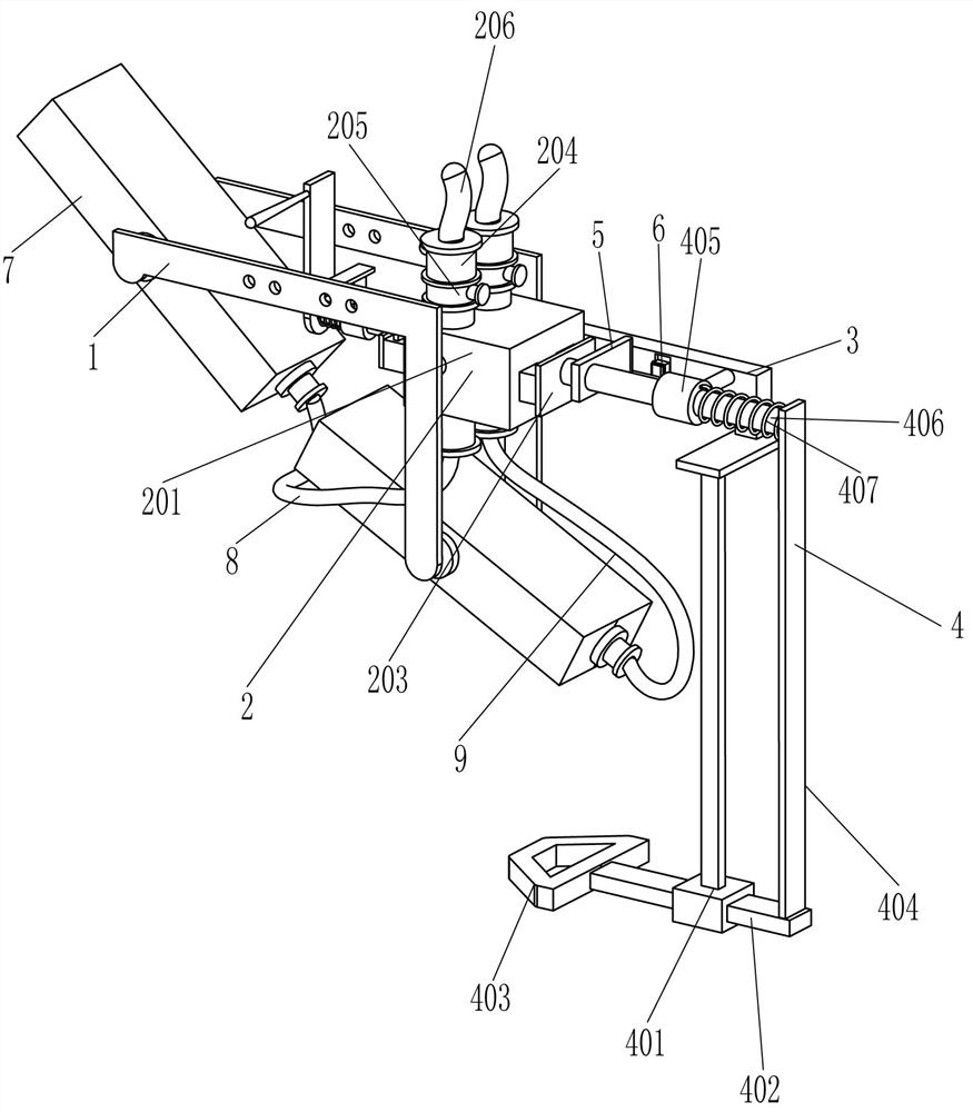
[0038] A kind of sole release agent spraying equipment, such as Figure 1-3 As shown, it includes an L-shaped mounting frame 1, a shut-off device 2, a mounting plate 3, a pulling device 4, a push plate 5, a control switch 6, a liquid sprayer 7, a first hose 8 and a second hose 9, and the shut-off device The front and rear sides of 2 are equipped with L-shaped mounting brackets 1, and the left and lower ends of the L-shaped mounting brackets 1 on both sides are connected to the liquid sprayer 7, and the right side of the left liquid sprayer 7 is connected to the bottom of the shut-off device 2 A first hose 8 is connected between them, a second hose 9 is connected between the right part of the right sprayer 7 and the bottom of the shut-off device 2, and a mounting plate 3 is provided on the right side of the rear L-shaped mounting frame 1, The middle part of the front side of the mounting plate 3 is provided with a control switch 6, and the right side of the shut-off device 2 is...

Embodiment 2

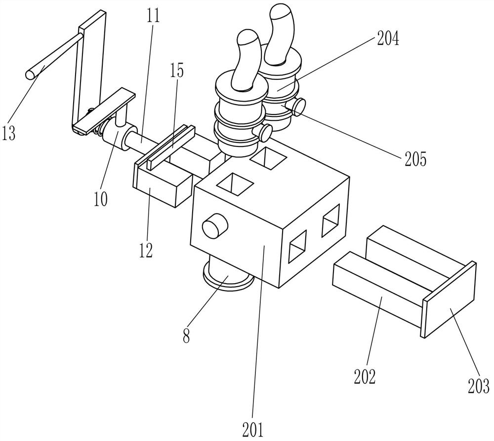
[0041] On the basis of Example 1, such as Figure 1-3 As shown, the intercepting device 2 includes a porous block 201, a retaining bar 202, a connecting plate 203, a liquid inlet pipe 204, a timing solenoid valve 205 and an infusion hose 206, and a porous block 201 is installed between the corners of the L-shaped mounting frame 1 on both sides. , the right wall and the top of the porous block 201 are provided with two connected square holes, the two square holes on the right side of the porous block 201 are slidingly provided with a retaining bar 202, the right end of the retaining bar 202 is provided with a connecting plate 203, the porous block Liquid inlet pipes 204 are arranged in the two square holes on the top of the 201, and a timing solenoid valve 205 is installed in the middle of the liquid inlet pipes 204, and an infusion hose 206 is provided at the upper ends of the two liquid inlet pipes 204.

[0042] When the pulling part of the pulling device 4 moves to the right...

Embodiment 3

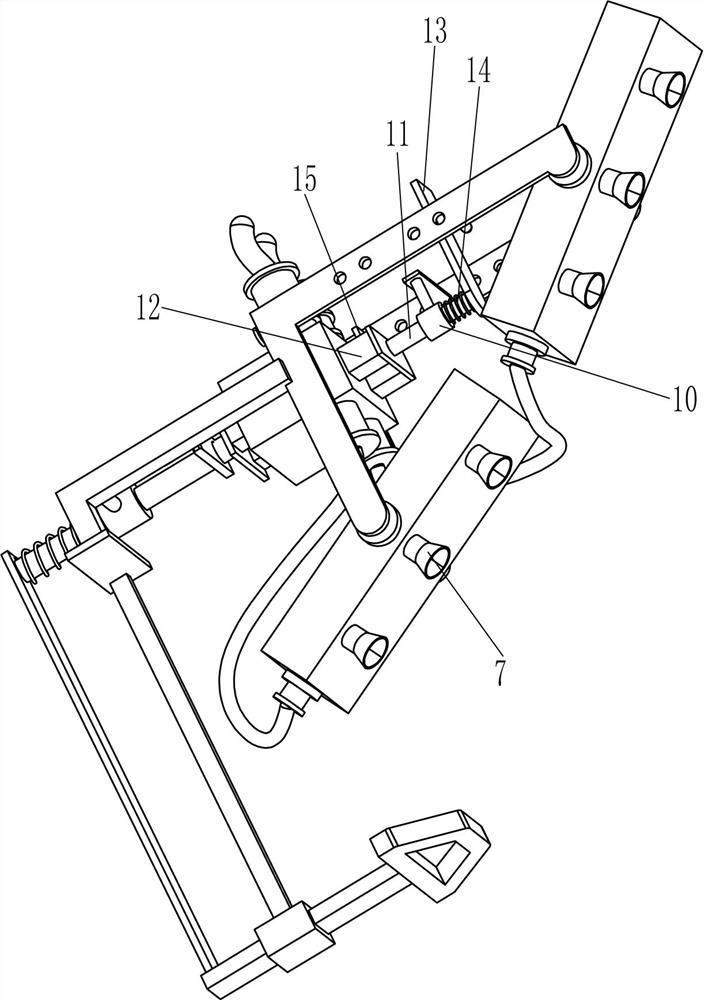
[0046] On the basis of Example 2, such as Figure 1-3 As shown, it also includes a third guide frame 10, a guide rod 11, an interceptor frame 12, a pull handle 13 and a second compression spring 14, and the two square holes on the left side of the porous block 201 are slidingly provided with an interceptor frame 12. A third guide frame 10 is installed on the rear side of the middle part of the side L-shaped mounting frame 1, and a guide rod 11 is slidably provided in the third guide frame 10. The left end of the rod 11 is provided with a pull handle 13, and a second compression spring 14 is connected between the right part of the pull handle 13 and the left part of the third guide frame 10, and the second compression spring 14 is wound on the guide rod 11.

[0047] When the mold needs to be cleaned, manually hold the pull handle 13 and push the guide rod 11 to the right, and the interceptor frame 12 then enters the multi-empty block to intercept the release agent to prevent th...


PUM


Abstract

The invention relates to a spraying device, in particular to a spraying device for a release agent for shoe soles. The technical problem to be solved is to provide a mold release agent spraying equipment for shoe soles that can replace manpower, automatically spray different mold release agents on the upper and lower molds, and will not spray the mold release agent in the wrong position. The technical solution of the present invention is a spraying equipment for shoe sole release agent, comprising: L-shaped mounting frame, a flow intercepting device is installed between the two L-shaped mounting frames; a liquid sprayer, between the left ends of the two L-shaped mounting frames and the lower end Liquid sprayers are installed between them; the first flexible pipe is connected between the side of the upper liquid sprayer near the side of the intercepting device and the bottom of the intercepting device. The present invention can realize the closure of the release agent through the interception device, and with the cooperation of the liquid sprayer, the spraying of the release agent can be realized automatically. At the same time, two liquid sprayers and infusion hoses are provided to realize the synchronization of the upper and lower molds Spraying, it is not easy to mix the release agents of the upper and lower molds.

Description

technical field [0001] The invention relates to a spraying device, in particular to a spraying device for a release agent for shoe soles. Background technique [0002] At present, when manufacturers produce shoe soles, they need to form shoe soles in the mold first, and then manually spray different release agents on the upper and lower molds to separate the shoe soles from the molds, making it easier for workers to take the shoe soles out of the mold. This method of spraying the release agent takes a lot of time for workers, and long-term spraying will also cause worker fatigue. If the worker accidentally sprays the two spraying agents in the wrong position, the sole may be damaged and cannot be completely separated from the mold. [0003] In order to solve the problem that the above-mentioned spraying method of shoe sole release agent consumes a lot of energy of workers, workers are prone to fatigue, and the release agent is easy to spray in the wrong position, it is neces...

Claims


Application Information

Patent Timeline
Patent Type & Authority Patents(China)
IPC IPC(8): B29C33/58B29L31/50
CPCB29C33/58B29L2031/504
Inventor 王永芳
Owner 江西正博实业有限公司
Why Eureka
Try Eureka