
A contact self-shielding anti-storm charging pile

A charging pile and self-shielding technology, applied in charging stations, electric vehicle charging technology, electric vehicles, etc., can solve the problems of inconvenient use, affecting the service life of charging piles, etc., and achieve easy protection, good market prospects, and easy control. Effect

Active Publication Date: 2020-11-06
CHANGZHOU INST OF DALIAN UNIV OF TECH
View PDF6 Cites 1 Cited by
  • Summary
  • Abstract
  • Description
  • Claims
  • Application Information

AI Technical Summary

Problems solved by technology

[0004] The purpose of the present invention is to provide a contact-type self-shielding anti-storm charging pile to solve the problem that the existing outdoor charging piles proposed in the above background technology are easy to be attacked by heavy rain, and the commonly used outdoor charging piles cannot be used in heavy rain. In the process, the charging interface is protected from rain, which is inconvenient to use and affects the service life of the charging pile.

Method used


Image

  • A contact self-shielding anti-storm charging pile
  • A contact self-shielding anti-storm charging pile
  • A contact self-shielding anti-storm charging pile

Examples


Embodiment 1

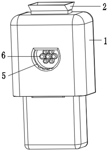
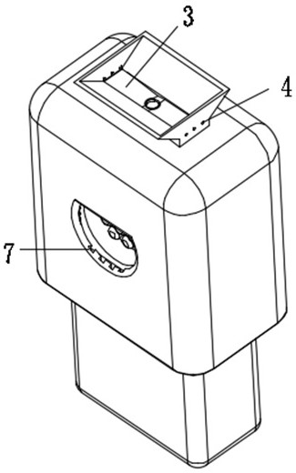
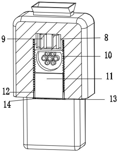
[0024] Embodiment 1: A specific application of this embodiment is: when the rainstorm comes, the present invention enables a large amount of rainwater to flow into the top of the water cover plate 18 through the setting of the rain receiving box 2 and the inclined plate 3, and by increasing the water cover plate The pressure on the top of 18 makes the water cover 18 compress the return spring 23 and move downward. When the water cover 18 reaches a certain position, the metal sheet 21 contacts the contact piece 22, so that the electromagnet 9 is energized, and the electromagnet 9 and the rain shield 11 magnetic adsorption, so that the rain shield 11 can overcome the elastic force of the long spring 10 to rise, and cover the charging jack 6, so as to prevent rainstorms and protect the charging jack 6.

Embodiment 2

[0025] Embodiment 2: A specific application of this embodiment is: the present invention will not make the charging jack 6 contact with water in sunny days and light rains. At this time, the water cover 18 is positioned at the circular The upper end of the cylinder cavity 17 makes the metal sheet 21 not contact with the contact piece 22, and the electromagnet 9 is de-energized. The lower end of the cavity 5 exposes the charging jack 6 and can be used by the user. When the rainstorm comes, a large amount of rainwater can flow into the top of the water cover 18 through the setting of the rain receiving box 2 and the inclined plate 3. By increasing the The pressure on the top of the water cover plate 18 makes the water cover plate 18 compress the return spring 23 and move downward. When the water cover plate 18 reaches a certain position, the metal sheet 21 contacts the contact piece 22, and the electromagnet 9 is energized, and the electromagnet 9 and The rain shielding plate 11...


PUM


Abstract

The invention discloses a contact-type self-shielding anti-storm charging pile in the technical field of charging piles. The side wall of the side cavity is provided with a side cavity, and the inner cavity of the side cavity is slidably provided with a rain shield, and two sets of bottom connecting blocks are fixedly installed on the side wall of the bottom end of the rain shield, and a long spring is fixedly installed on the top of the bottom connecting block. The top of the spring is fixedly connected with the top of the side cavity, and an installation cavity is arranged above the side cavity, and two groups of electromagnets are fixedly installed in the inner cavity of the installation cavity, the electromagnets are magnetically matched with the rain shield, and the bottom of the rain bearing box is provided with a circular Cylinder cavity, the bottom of the cylinder cavity is fixed with a return spring, and the inner cavity of the cylinder cavity is slidingly matched with a water cover. This device can prevent heavy rain, protect the charging jack, and automatically open the protection when it rains , easy to control, and has a good market prospect.

Description

technical field [0001] The invention relates to the technical field of charging piles, in particular to a contact-type self-shielding anti-storm charging pile. Background technique [0002] Existing outdoor charging piles are vulnerable to heavy rain, and commonly used outdoor charging piles cannot cover the charging interface in heavy rain, which is inconvenient to use and affects the service life of the charging pile. [0003] Based on this, the present invention designs a contact-type self-shielding anti-storm charging pile to solve the above problems. Contents of the invention [0004] The purpose of the present invention is to provide a contact-type self-shielding anti-storm charging pile to solve the problem that the existing outdoor charging piles proposed in the above background technology are easy to be attacked by heavy rain, and the commonly used outdoor charging piles cannot be used in heavy rain. In the middle, the charging interface is protected from rain, w...

Claims


Application Information

Patent Timeline
Patent Type & Authority Patents(China)
IPC IPC(8): B60L53/31H05K5/02
CPCB60L53/31H05K5/0217H05K5/0247H05K5/03Y02T10/70Y02T10/7072Y02T90/12
Inventor 李强
Owner CHANGZHOU INST OF DALIAN UNIV OF TECH
Learn More