
Multifunctional battery bracket for new energy automobile

A new energy vehicle and battery bracket technology, which is applied in the field of new energy vehicles, can solve the problems of no protective structure, difficult installation and disassembly of the battery bracket, and vulnerability to vibration and collision, so as to improve the convenience of use and facilitate loading or disassembly , the effect of improving safety

Inactive Publication Date: 2019-10-15
界首尚嘉工业设计有限公司
View PDF0 Cites 9 Cited by
  • Summary
  • Abstract
  • Description
  • Claims
  • Application Information

AI Technical Summary

Problems solved by technology

[0003] Ordinary battery brackets fix the battery on the chassis of the car. It is a rigid connection without a corresponding protective structure. It is vulnerable to vibration and collision during use, resulting in damage to the battery. Moreover, it is difficult to install and disassemble the ordinary battery bracket, which is inconvenient. Repair the battery in it, and the power and energy of the battery used in the car are high, and the heat is generated during use. The general battery bracket does not have a corresponding heat dissipation structure, and an additional heat dissipation system is required, which is insufficient in functionality, and the car When the battery is damaged or the temperature is too high, it is very easy to catch fire and cause an explosion. Most battery brackets do not have corresponding self-extinguishing and explosion-proof structures, and the safety is insufficient.

Method used


Image

  • Multifunctional battery bracket for new energy automobile
  • Multifunctional battery bracket for new energy automobile
  • Multifunctional battery bracket for new energy automobile

Examples


Embodiment Construction

[0032] The following will clearly and completely describe the technical solutions in the embodiments of the present invention with reference to the accompanying drawings in the embodiments of the present invention. Obviously, the described embodiments are only some, not all, embodiments of the present invention.

[0033]In the description of the present invention, unless otherwise stated, the meaning of "plurality" is two or more; the terms "upper", "lower", "left", "right", "inner", "outer" , "front end", "rear end", "head", "tail", etc. indicate the orientation or positional relationship based on the orientation or positional relationship shown in the drawings, and are only for the convenience of describing the present invention and simplifying the description, rather than Nothing indicating or implying that a referenced device or element must have a particular orientation, be constructed, and operate in a particular orientation should therefore not be construed as limiting t...


PUM


Abstract

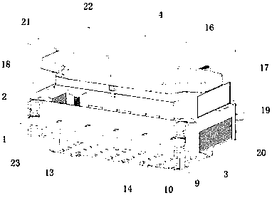
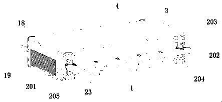
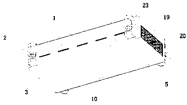
The invention discloses a multifunctional battery bracket for a new energy automobile, and relates to the technical field of new energy automobiles. The multifunctional battery bracket comprises a mounting frame and an air box, a buffering and shockproof mechanism is mounted at the middle portion of the mounting frame, a sealing shell is connected at the middle portion of the buffering and shockproof mechanism, a top cover is fixed at the upper portion of the sealing shell, a loading and unloading opening is formed below the sealing shell, a lifting motor is mounted in the sealing shell, and the shaft end of the lifting motor is connected with a stud. The multifunctional battery bracket for a new energy automobile is provided with the buffering and shockproof mechanism which is connected with the mounting frame and the sealing shell, the device is provided with the sealing shell, the sealing shell can package a battery in the sealing shell to protect the battery, the mounting frame isinstalled on an automobile chassis, a connection frame is fixed on the mounting frame and is capable of vertically moving on a sliding column through a sliding sleeve and can be subjected to buffer and shock absorption through a spring, so that when the sealing shell is impacted and shocked, buffering and shock absorption are performed to protect the battery loaded in the sealing shell to facilitate improvement of the safety of the device.

Description

technical field [0001] The invention relates to the technical field of new energy vehicles, in particular to a multifunctional battery bracket for new energy vehicles. Background technique [0002] Cars are one of the most important means of transportation for human beings. Due to the fossil energy crisis and environmental pollution, traditional fuel vehicles will gradually be eliminated, and new energy vehicles will replace fuel vehicles. New energy vehicles refer to unconventional vehicles. Using fuel as the power source, combining the advanced technology of vehicle power control and driving, the vehicle with advanced technical principle, new technology and new structure is formed. Most new energy vehicles are driven by electricity and need to be loaded with a large number of batteries for the vehicle. The battery is generally installed on the chassis of the car through the battery bracket. [0003] Ordinary battery brackets fix the battery on the chassis of the car. It i...

Claims


Application Information

Patent Timeline
IPC IPC(8): H01M2/10H01M2/12H01M10/613H01M10/625H01M10/635H01M10/6551H01M10/6556H01M10/6561H01M10/6568A62C3/16
CPCA62C3/16H01M10/613H01M10/625H01M10/635H01M10/6551H01M10/6556H01M10/6561H01M10/6568H01M50/20H01M50/24H01M50/333Y02E60/10
Inventor 郭平
Owner 界首尚嘉工业设计有限公司
Learn More