
Control method and device for automatic multi-mode image compression

A control method and image compression technology, applied in the field of image processing, can solve the problems of large memory, waste of traffic resource storage resources, increase of circuit cost, etc., and achieve the effect of simple operation, high commercial value, and convenient use

Inactive Publication Date: 2020-09-11
NEW VISION MICROELECTRONICS INC
View PDF5 Cites 0 Cited by
  • Summary
  • Abstract
  • Description
  • Claims
  • Application Information

AI Technical Summary

Problems solved by technology

[0003] The advancement of technology has also greatly improved the definition of photos, but while improving the definition, the format of photos is getting larger and larger, and the memory occupied is also increasing. Similarly, these pictures with larger memory Sharing will inevitably result in a waste of traffic resources and storage resources on the receiving side. Therefore, how to compress the image without destroying the original image has become a topic that people pay more attention to at present.
[0004] At present, the industry that implements image fixed-ratio compression is mainly the DSC algorithm developed by the VESA Association. This algorithm can achieve a fixed-ratio compression of one-third and one-half of an image, and can achieve visually lossless, but the existing DSC The compression operation is more complicated, and the image compression needs to rely on the previous row of image data, that is, the operation circuit needs to store an extra row of data, which increases the cost of the circuit
[0005] At present, there is no control method and device for automatic multi-mode image compression in the market

Method used


Image

  • Control method and device for automatic multi-mode image compression
  • Control method and device for automatic multi-mode image compression
  • Control method and device for automatic multi-mode image compression

Examples


Embodiment Construction

[0062] In order to better clearly express the technical solution of the present invention, the present invention will be further described below in conjunction with the accompanying drawings.

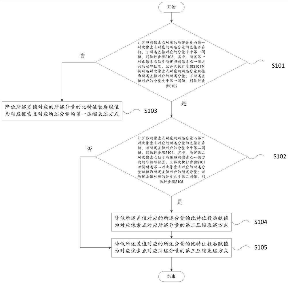
[0063] figure 1 It shows a specific embodiment of the present invention, a specific flowchart of an automatic multi-mode image compression control method. The present invention compresses the original image data based on the components of different pixels to obtain compressed image data. Those skilled in the art It is understood that each image is composed of tens of thousands of pixels, and the pixels are composed of three primary colors of red, green, and blue, that is, when the three colors of red, green, and blue are arbitrarily The combination is to form the different color display of each pixel, so in the binary representation, it is preferable to assign the red, green and blue components in each pixel, which are recorded as R value, G value and B value respectively , that is, th...


PUM


Abstract

The invention provides a control method for automatic multi-mode image compression. The method comprises the following steps: a, calculating and storing a difference value between a component corresponding to a current pixel point and a component corresponding to a first comparison pixel point, b, calculating and storing a difference value between the component corresponding to the current pixel point and the component corresponding to the second comparison pixel point, if the component corresponding to the difference value is smaller than a second threshold value, executing a step d, and if the component corresponding to the difference value is larger than the second threshold value, executing a step e; c, after the bit number of the component corresponding to the difference value is reduced, assigning a first compression expression mode of the component corresponding to the corresponding pixel point; d, after the bit number of the component corresponding to the difference value is reduced, assigning a second compression expression mode of the component corresponding to the corresponding pixel point; and e, after the bit number of the component corresponding to the current pixel point is reduced, assigning a third compression expression mode of the component corresponding to the corresponding pixel point. The method and devie are simple to operate and convenient to use, and have extremely high commercial value.

Description

technical field [0001] The invention relates to the field of image processing, in particular to a control method and device for automatic multi-mode image compression. Background technique [0002] With the development of life and the advancement of science and technology, people's living standards have gradually improved, and with the popularization of the Internet, people's daily life has also undergone earth-shaking changes. In the past, people usually communicated by phone or text message. With the release of more and more social software, people began to communicate with each other through the Internet, and more fun was derived, and sharing their photos and experiences has become a living habit of people. [0003] The advancement of technology has also greatly improved the definition of photos, but while improving the definition, the format of photos is getting larger and larger, and the memory occupied is also increasing. Similarly, these pictures with larger memory S...

Claims


Application Information

Patent Timeline
Patent Type & Authority Applications(China)
IPC IPC(8): H04N19/186H04N19/184H04N19/42
CPCH04N19/184H04N19/186H04N19/42
Inventor 肖宏
Owner NEW VISION MICROELECTRONICS INC
Learn More