Automobile rescue auxiliary device
An auxiliary device and vehicle rescue technology, which is applied in distribution devices, special distribution devices, liquid distribution, transportation or transfer devices, etc., can solve inconvenience and other problems, and achieve the effect of facilitating oil transportation
- Summary
- Abstract
- Description
- Claims
- Application Information
AI Technical Summary
Problems solved by technology
Method used
Image
Examples
specific Embodiment approach 1
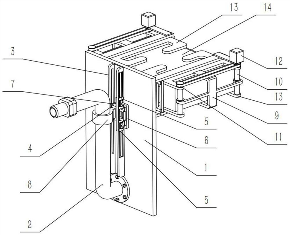
[0036] Combine below Figure 1-12Describe this embodiment, an auxiliary device for automobile rescue, including a main support plate 1, an oil delivery pipe 2 and an oil storage bag 14, the lower middle part of the oil delivery pipe 2 is fixedly connected to the middle part of the main support plate 1, and the oil storage bag 14 The bag 14 is fixed and connected to the right side of the oil delivery pipe 2. The vehicle rescue auxiliary device also includes an adjustment slideway 3, an adjustment slide plate 4, a top tightening mechanism 5, an adjustment handle 6, an auxiliary pulley 7, an adjustment connection sleeve 8, and a cross connection frame 9. Adjustment screw 10, transmission belt 11, motor 12 and extrusion frame 13, the adjustment slide 3 is fixedly connected to the left side of the main support plate 1, and the adjustment slide 4 is slidably connected to the adjustment slide 3 Inside, the said tightening mechanism 5 is provided with two, and the two tightening mecha...
specific Embodiment approach 2
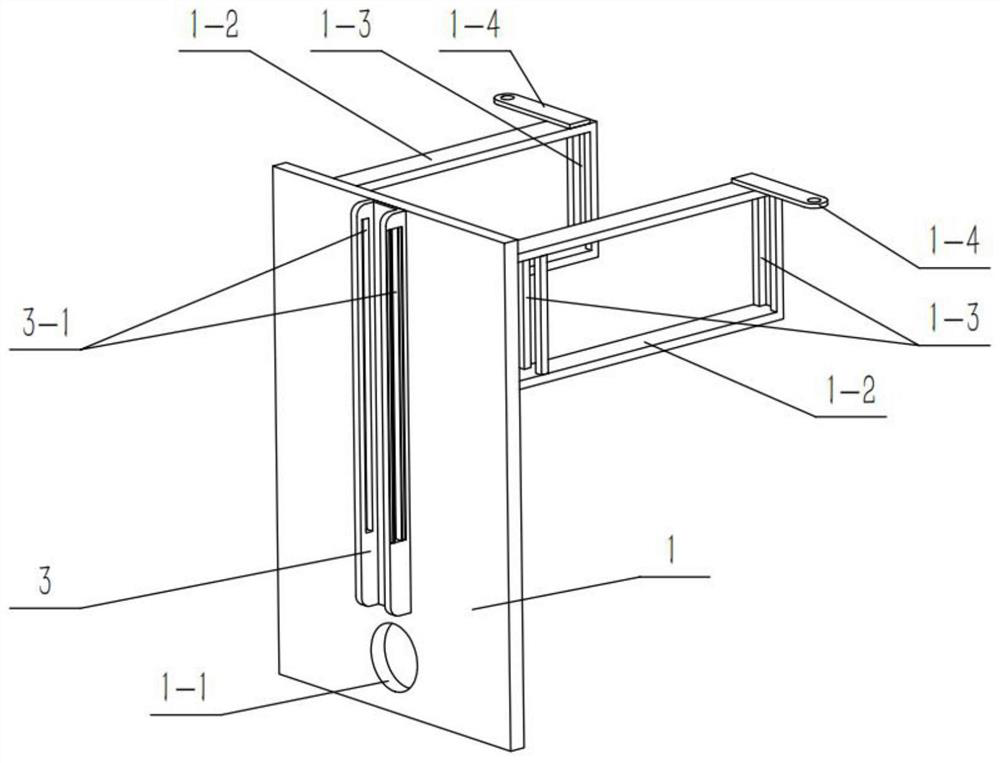
[0039] Combine below Figure 1-12 This embodiment will be described. This embodiment will further describe the first embodiment. The lower part of the main support plate 1 is provided with an installation hole 1-1, and the lower part of the oil delivery pipe 2 is fixedly connected in the installation hole 1-1. The front and rear ends of the upper right side are fixedly connected with a positioning frame 1-2, the left and right ends of the positioning frame 1-2 are provided with slideways 1-3, and the two positioning frames 1-2 are symmetrically provided with motors. Plate 1-4, each motor plate 1-4 is provided with a motor 12, two cross connectors 9 are fixedly connected with two positioning frames 1-2 respectively, and the two sides of the extrusion frame 13 are slidingly connected to the corresponding Inside the chute 1-3.
specific Embodiment approach 3
[0041] Combine below Figure 1-12 Describe this embodiment, this embodiment will further explain Embodiment 2, the oil delivery pipe 2 is a hose, the lower part of the oil delivery pipe 2 is provided with a connecting part 2-1, and the connecting part 2-1 is fixedly connected to the installation hole 1-1, the upper right part of the oil delivery pipe 2 is provided with an oil delivery end 2-2.
PUM
 Abstract
Description
Claims
Application Information
 - R&D
- Intellectual Property
- Life Sciences
- Materials
- Tech Scout
- Unparalleled Data Quality
- Higher Quality Content
- 60% Fewer Hallucinations
Browse by: Latest US Patents, China's latest patents, Technical Efficacy Thesaurus, Application Domain, Technology Topic, Popular Technical Reports.
© 2025 PatSnap. All rights reserved.Legal|Privacy policy|Modern Slavery Act Transparency Statement|Sitemap|About US| Contact US: help@patsnap.com


