Beef ball making equipment
A technology of beef balls and equipment, which is applied in the fields of processing meat, slaughtering, food science, etc., can solve the problems of sanitation and time-consuming production
- Summary
- Abstract
- Description
- Claims
- Application Information
AI Technical Summary
Problems solved by technology
Method used
Image
Examples
Embodiment 1
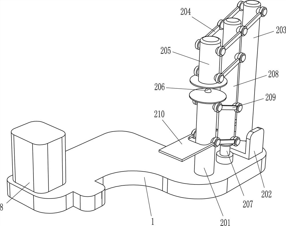
[0062] A kind of equipment for making beef balls, such as Figure 1-2 As shown, it includes a base 1, a pressing mechanism 2, a feeding mechanism 3, a fixed rod 4, a charging sleeve 5, a hemispherical trough block 6 and a first elastic member 7, and the right side of the base 1 is provided with a pressing mechanism 2 , the rear left side of the base 1 is provided with a feeding mechanism 3, the feeding mechanism 3 is provided with a fixed rod 4, the front part of the fixed rod 4 is provided with a charging sleeve 5 slots, and the lower part of the left side of the charging sleeve 5 is provided with The first elastic member 7 is connected with the hemispherical trough block 6, and the hemispherical material is placed at the bottom of the charging sleeve 5.
[0063]When people need to make beef balls, the beef material is first added to the charging sleeve 5 and the hemispherical trough block 6, and then the parts of the feeding mechanism 3 are manually rotated, and the parts of...
Embodiment 2
[0065] On the basis of Example 1, such as Figure 3-5 As shown, the pressing mechanism 2 includes a cylindrical seat 201, a mounting seat 202, a swing rod 203, a connecting long rod 204, a weight 205, a hemispherical groove block 206, a guide sleeve 207, a sliding rod 208, a connecting rod 209 and a pedal 210 , the right front of the base 1 is provided with a cylindrical seat 201, the left and right sides of the upper part of the cylindrical seat 201 and the left and right sides of the lower part are rotatably connected with connecting rods 209, and the rear sides of the connecting rods 209 are rotatably connected with sliding rods 208, and the base 1. A guide sleeve 207 is provided at the rear of the right side. The bottom of the sliding rod 208 is in contact with the guide sleeve 207. A pedal 210 is connected between the front parts of the connecting rod 209 on the lower side. The long rod 204 is connected to the front side of the long rod 204 and is connected with a weight ...
Embodiment 3
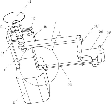
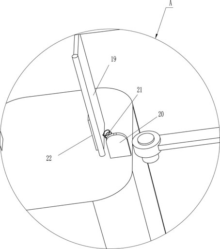
[0070] On the basis of Example 2, such as Figure 5-7 As shown, it also includes a fixed block 8, a connecting frame 9, a U-shaped frame 10, a lower hopper 11, a guide rail 13, an N-shaped frame 14, a block 15, a second elastic member 16, a material blocking plate 17 and an L-shaped connecting rod 18 , a fixed block 8 is installed on the front left side of the base 1, a connecting frame 9 is connected to the front side of the top of the fixed block 8, a U-shaped frame 10 is arranged on the top of the connecting frame 9, and a lower hopper 11 is connected to the rear side of the U-shaped frame 10, and the lower hopper 11. There are two through slots 12 on the lower side. The back side of the lower hopper 11 is connected with a U-shaped frame 10. The lower side through slot 12 is located in the middle of the front side U-shaped frame 10. The upper side through slot 12 is located in the rear side U-shaped frame. In the middle of 10, the bottom of the lower hopper 11 and the top o...
PUM
 Abstract
Description
Claims
Application Information
 - R&D
- Intellectual Property
- Life Sciences
- Materials
- Tech Scout
- Unparalleled Data Quality
- Higher Quality Content
- 60% Fewer Hallucinations
Browse by: Latest US Patents, China's latest patents, Technical Efficacy Thesaurus, Application Domain, Technology Topic, Popular Technical Reports.
© 2025 PatSnap. All rights reserved.Legal|Privacy policy|Modern Slavery Act Transparency Statement|Sitemap|About US| Contact US: help@patsnap.com


