
Putty smearing equipment

A technology of putty and equipment, applied in the direction of building, building structure, etc., can solve the problems of low reliability, low putty efficiency, trouble, etc., and achieve the effect of improving work efficiency and simple structure

Inactive Publication Date: 2020-09-18
齐嘉蕾
View PDF5 Cites 0 Cited by
  • Summary
  • Abstract
  • Description
  • Claims
  • Application Information

AI Technical Summary

Problems solved by technology

[0002] In the process of applying putty on the wall, the existing equipment and working methods often use a shovel to apply the putty on the wall by hand and fully spread the putty on the wall so that the putty on the wall can be fully distributed on the wall. , but in the existing equipment, the putty is also sprayed on the wall by spraying. The common disadvantage of the above methods is that because the above-mentioned process cannot achieve quantitative spraying of the putty on the wall, manual active intervention and control are required. This has just caused a large amount of waste of putty, and at the same time, because the above-mentioned process is less reliable in actual work, it requires personnel to pay too much attention to whether it has been applied, and to apply putty for some higher areas, or personnel use ladders In order to realize the efficient smearing of putty, but this requires personnel to carry out high-altitude operations. When personnel perform high-altitude operations, the disadvantages caused by this are more obvious, which endangers the personal safety of personnel and causes unnecessary troubles, which makes personnel Reduced efficiency in applying putty

Method used


Image

  • Putty smearing equipment
  • Putty smearing equipment
  • Putty smearing equipment

Examples


Embodiment Construction

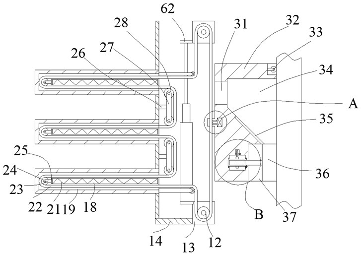
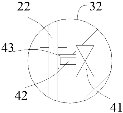
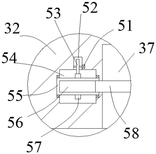
[0025] like Figure 1-Figure 5 As shown, the present invention is described in detail. For the convenience of description, the orientations mentioned below are now stipulated as follows: figure 1 The up, down, left, right, front and back directions of the projection relationship itself are consistent. The putty smearing equipment of the present invention includes a box body 14, and a plurality of open side chambers 19 are arranged in the box body 14. One side of the box body 14 is provided with a matching box body 32. A putty scraping device that fits the wall surface to scrape putty and can close the putty pouring port is provided in the opposing box body 32. The box body 14 and the side inner cavity 19 are provided with a putty scraping device that is used for telescopic changes. The above-mentioned counteracting box body 32 can move to any height and can save the telescopic transmission device of equipment space.

[0026] Beneficially, wherein, the putty scraping device in...


PUM


Abstract

The invention discloses putty smearing equipment. The putty smearing equipment comprises a box body, a plurality of side inner cavities with openings are formed in the box body, an abutting box body is arranged on one side of the box body, a puttying device which is attached to a wall surface for puttying and can seal a putty pouring opening is arranged in the abutting box body, and a telescopic transmission device is arranged in the box body and the side inner cavities, wherein when the telescopic transmission device telescopically changes, the abutting box body can move to any height, and the equipment space can be saved. The equipment is simple in structure, the design of capable of performing stable ascending and descending is adopted so that the structure capable of performing putty smearing can still abut against the wall surface to extrude putty to achieve all-dimensional putty smearing after ascending and descending, manual smearing is replaced so that quantitative putty smearing can be achieved, and the working efficiency of the equipment is greatly improved.

Description

technical field [0001] The invention relates to the technical field of putty smearing equipment, in particular to putty smearing equipment. Background technique [0002] In the process of applying putty on the wall, the existing equipment and working methods often use a shovel to apply the putty on the wall by hand and fully spread the putty on the wall so that the putty on the wall can be fully distributed on the wall. , but in the existing equipment, the putty is also sprayed on the wall by spraying. The common disadvantage of the above methods is that because the above-mentioned process cannot achieve quantitative spraying of the putty on the wall, manual active intervention and control are required. This has just caused a large amount of waste of putty, and at the same time, because the above-mentioned process is less reliable in actual work, it requires personnel to pay too much attention to whether it has been applied, and to apply putty for some higher areas, or perso...

Claims


Application Information

Patent Timeline
IPC IPC(8): E04F21/08
CPCE04F21/08
Inventor 齐嘉蕾
Owner 齐嘉蕾
Learn More