
A hysteresis driven damper

A driving and hysteresis technology, which is applied in the direction of lifting valves, valve devices, engine components, etc., can solve the problems of no sealing protection structure and hidden dangers in the sealing effect, and achieve the effect of avoiding accidental rotation

Active Publication Date: 2021-12-14
江苏磊霆精密新材料有限公司
View PDF0 Cites 0 Cited by
  • Summary
  • Abstract
  • Description
  • Claims
  • Application Information

AI Technical Summary

Problems solved by technology

[0002] The damper is a regulating valve with a relatively simple structure, which is usually used to cut off or throttle the air flow in the pipeline; the existing damper generally includes a valve body, a valve plate, a driving rod, and a sealing ring; the sealing ring is installed on the valve body Inside, the valve plate is sealed or separately connected to the sealing ring inside the valve body, and then the driving rod extends downward from the upper end of the valve body to the upper end of the valve plate inside the valve body, by rotating the driving rod, the driving rod drives the valve plate to rotate, thereby It can complete the opening and closing or separation process around the outer side of the valve plate and the inner wall of the inner sealing ring of the valve body; but the above air valve structure has only one valve plate as the sealing part, and there is no multiple sealing protection structure, so that the sealing effect has hidden dangers

Method used


Image

  • A hysteresis driven damper
  • A hysteresis driven damper
  • A hysteresis driven damper

Examples


Embodiment Construction

[0022] The content of the present invention will be further described in detail below in conjunction with the accompanying drawings.

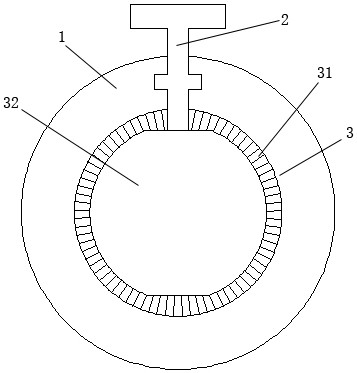
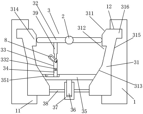
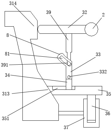
[0023] Such as Figures 1 to 7 As shown, a hysteresis-driven air valve includes a valve body 1, a drive rod 2, and a hysteresis-response sealing mechanism 3; 35. Rotating rod 39, sliding telescopic rod 34, guide column 36, guide cylinder 37, connecting rod 38, arc-shaped block 8; the sealing ring 31 is installed inside the valve body 1; the inner end of the sealing ring 31 is surrounded by The inside is provided with an inner sealing convex ring 314; the inner side of the outer end of the sealing ring 31 is provided with a tapered sealing ring surface 313; the tapered sealing ring surface 313 is a conical structure with a large inner end and a small outer end; The outer end closure plate 35 is a flat conical structure; the inner end closure plate 32 is installed inside the inner sealing convex ring 314 at the inner end of the sealing ring 31; ...


PUM


Abstract

The invention discloses a hysteresis drive type air valve, comprising a valve body, a drive rod and a hysteresis response type sealing mechanism; the hysteresis response type sealing mechanism comprises a sealing ring, an inner end closing plate, an outer end closing plate, a rotating rod, a sliding Telescopic rod, guide column, guide cylinder, connecting rod, and arc-shaped block; in the present invention, when the rotating rod rotates, the outer end of the rotating rod is slidably clamped to the arc-shaped idling slide inside the arc-shaped block through the sliding clamp joint. In the groove, the rotating rod is idling on the arc-shaped block for a certain distance, that is, the rotating rod slides arc-shaped on the arc-shaped idling chute inside the arc-shaped block through the sliding card joint at the outer end, and the outer end is closed at this time. The plate and the conical sealing ring surface are still kept in sealing contact, so that when the driving rod rotates to a certain degree due to accident, the sealing contact between the outer end closing plate and the conical sealing ring surface can also be maintained, so as to avoid accidental rotation. effect.

Description

technical field [0001] The invention relates to a hysteresis driven damper. Background technique [0002] The damper is a regulating valve with a relatively simple structure, which is usually used to cut off or throttle the air flow in the pipeline; the existing damper generally includes a valve body, a valve plate, a driving rod, and a sealing ring; the sealing ring is installed on the valve body Inside, the valve plate is sealed or separately connected to the sealing ring inside the valve body, and then the driving rod extends downward from the upper end of the valve body to the upper end of the valve plate inside the valve body, by rotating the driving rod, the driving rod drives the valve plate to rotate, thereby It can complete the opening and closing or separation process around the outer side of the valve plate and the inner wall of the inner sealing ring of the valve body; but the above air valve structure has only one valve plate as the sealing part, and there is no...

Claims


Application Information

Patent Timeline
Patent Type & Authority Patents(China)
IPC IPC(8): F16K1/226F16K1/32F16K1/44
CPCF16K1/223F16K1/226F16K1/2263F16K1/32F16K1/44
Inventor 朱银德
Owner 江苏磊霆精密新材料有限公司
Learn More