Ratcheting strap with take-up reel

Inactive Publication Date: 2018-01-09
REMINGTON IND
View PDF16 Cites 9 Cited by
  • Summary
  • Abstract
  • Description
  • Claims
  • Application Information

AI Technical Summary

Benefits of technology

[0011]The invention may also be embodied in or practiced using a ratcheting strap device with an elongate body having a reel axis towards a first end and a ratcheting mechanism towards a second end opposite there-from. The ratcheting mechanism may be affixed to the body, and have a spool axis and a ratchet spool rotatable relative to the body there-about. The device may include a first strap/hook member having a first length of strap affixed to a first one of the ratcheting mechanism, and having a first hook affixed to a first distal end there-of. A take-up reel may be affixed to the body and rotational relative thereto about the reel axis. The device may include a second strap hook member with a second length of strap having a second proximal end connectable to the take-up reel, having a take-up strap portion adjacent to the second proximal end and windable around the take up reel, and having a second hook affixed to a second distal end there-of. The second length of strap may have a midsection between its second proximal and distal ends, passing through and engageable by the ratchet spool such that rotation of the spool causes the midsection to be wound there-around. The take up reel m

Problems solved by technology

Because prior art ratchet straps lack any effective means for efficiently and neatly being stored, except for rolling the webbing up around the ratcheting mechanism and wrapping with an elastic band or such, users often release and remove the webbing therefrom after every use.
Obviously, this storage arrangement poses problems, not limited to the inability t

Method used


Image

  • Ratcheting strap with take-up reel
  • Ratcheting strap with take-up reel
  • Ratcheting strap with take-up reel

Examples


Embodiment Construction

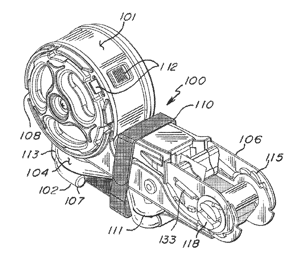
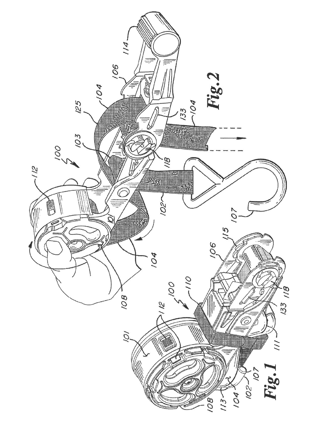
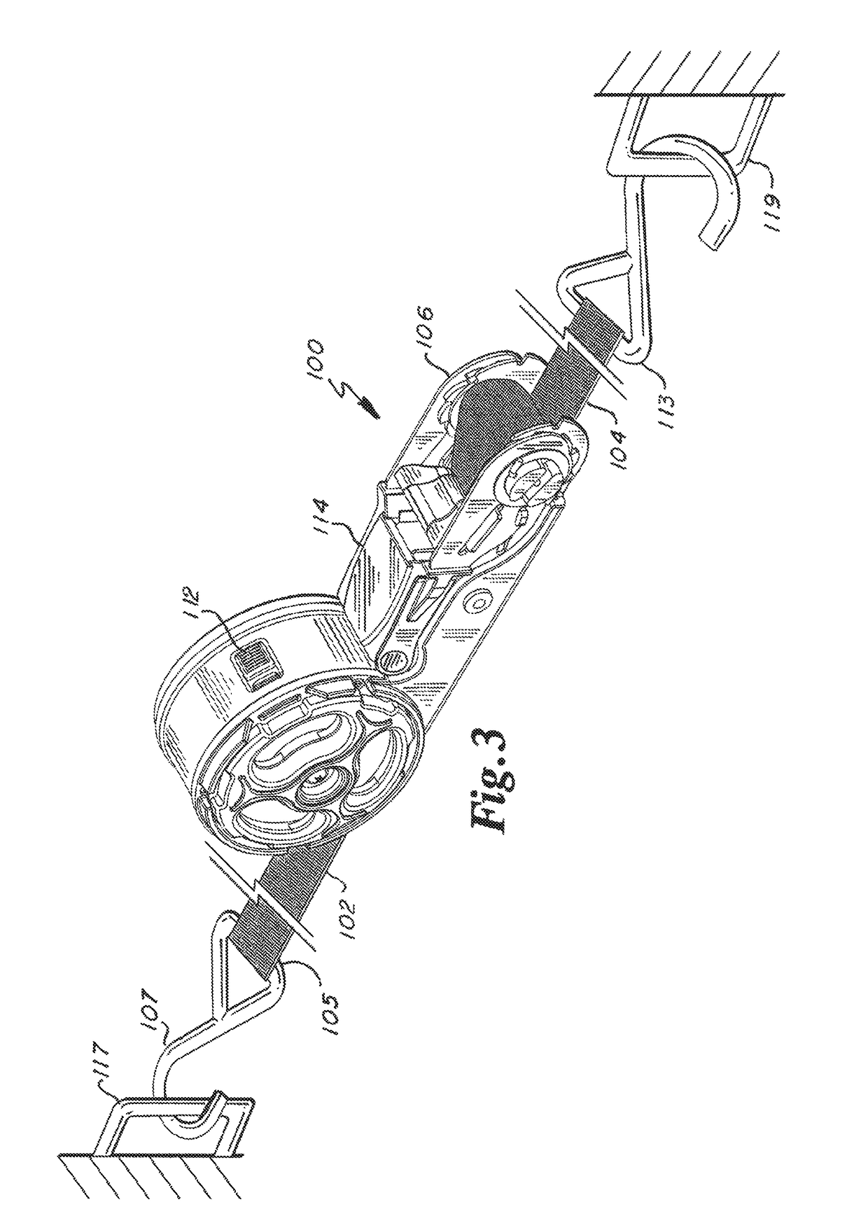
[0024]Referring to FIGS. 1 through 8, an exemplary ratcheting strap 100 according to or for use in practicing the invention is disclosed. The ratcheting strap includes a body 101, a short strap / hook 102, a long strap / hook 104, a ratchet mechanism 106, a take-up reel 108 for storing and dispensing the long strap / hook through the ratcheting mechanism, and a hook / loop belt 110 for retaining the ratcheting mechanism and straps / hooks in a compact configuration for storage. The short strap / hook has a proximal end 103 affixed to the body and ratcheting mechanism and a distal end 105 equipped with a hook 107. The long strap / hook has a proximal end 109 connected to the reel and a distal end 111 equipped with a hook 113.

[0025]FIG. 1 shows the ratcheting strap in its storage configuration with belt 110 wrapped around the straps / hooks and ratcheting mechanism. The take-up portion 135 of the long strap / hook closest to its distal end is wound around reel 108. Pawl 112 is slidable sideways to lock...


PUM


Abstract

A ratcheting strap device has an elongate body with a reel axis towards a first end and a ratcheting mechanism towards a second end opposite there-from. The ratcheting mechanism is affixed to the body, and has a spool axis and a ratchet spool rotatable relative to the body there-about. A first strap/hook member has a first length of strap affixed to a first one of the ratcheting mechanism and the body at a first proximal end, and has a first hook affixed to a first distal end there-of. A take-up reel is affixed to the body and rotational relative thereto about the reel axis. A second strap hook member has a second length of strap having a second proximal end connectable to the take-up reel, has a take-up strap portion adjacent to the second proximal end and windable around the take up reel, and has a second hook affixed to a second distal end there-of. The second length of strap has a midsection between its second proximal and distal ends, passing through and engageable by the ratchet spool such that rotation of the spool causes the midsection to be wound there-around.

Description

RELATED APPLICATIONS[0001]This application claims all entitled Priority to U.S. Provisional Applications No. 62 / 413,023 filed on 26 Oct. 2016, and No. 62 / 414,758 filed on 30 Oct. 2016, the entire teachings of which are incorporated herein by reference.FIELD OF THE INVENTION[0002]The present invention is related to devices and systems for securing one or more objects to one or more others. More specifically, the present invention is related to securement straps, such as ratcheting straps, for securing one or more articles, such as to or within a vehicle.BACKGROUND[0003]Ratcheting straps can be used to secure a wide variety of objects to various support surfaces and / or to various other objects. Typically, such straps are used to keep an object from falling or moving relative to a vehicle during transport. Such ratcheting straps typically have two portions; a long strap / hook, and a ratcheting strap sub-assembly including a short strap hook. Each strap / hook has a hook at one end which a...

Claims


Application Information

Patent Timeline
IPC IPC(8): B60P7/08B65H54/58B65H75/44B60P7/06B60P7/00B65H54/00
CPCB60P7/0846B65H54/585B65H75/4494B60P7/06B60P7/00B65H54/00B65H75/40B65H75/4431B65H75/4471B65H2701/375B60P7/083
Inventor ANDERSON, ERIK EDWARD
Owner REMINGTON IND
Why Eureka
Try Eureka