Rotatable hitch mountable load carrier

Active Publication Date: 2006-12-07
THULE SWEDEN AB
View PDF10 Cites 21 Cited by
  • Summary
  • Abstract
  • Description
  • Claims
  • Application Information

AI Technical Summary

Benefits of technology

[0007] The present invention incorporates several features that minimize the disadvantages outlined above, particularly with respect to the uncontrolled shifting of a load carrier, which can cause damage to equipment or the transporting vehic

Problems solved by technology

A problem with these devices, however, is that their extending arms can tend to rotate, or sag, at their hinged connections.
Additionally, as the number of hinged connections increases, or as the weight of equipment loaded upon the extending arms increases, sagging may become more pronounced.
This can be problematic because sagging tends to angularly displace the upright load supporting members, from their preferred vertical orientation.
When this occurs, it can be difficult to properly latch the load supporting member to a stationary portion of the carrier, which is typically connected to the vehicle's hitch receiver

Method used


Image

  • Rotatable hitch mountable load carrier
  • Rotatable hitch mountable load carrier
  • Rotatable hitch mountable load carrier

Examples


Example

[0021] As required, detailed embodiments of the present invention are disclosed herein; however, it is to be understood that the disclosed embodiments are merely exemplary and that the present invention may be embodied in various and alternative forms. The figures are not necessarily to scale; some features may be exaggerated or minimized to show details of particular components. Therefore, specific structural and functional details disclosed herein are not to be interpreted as limiting, but merely as a basis for the claims and as a representative basis for teaching one skilled in the art to variously employ the present invention.

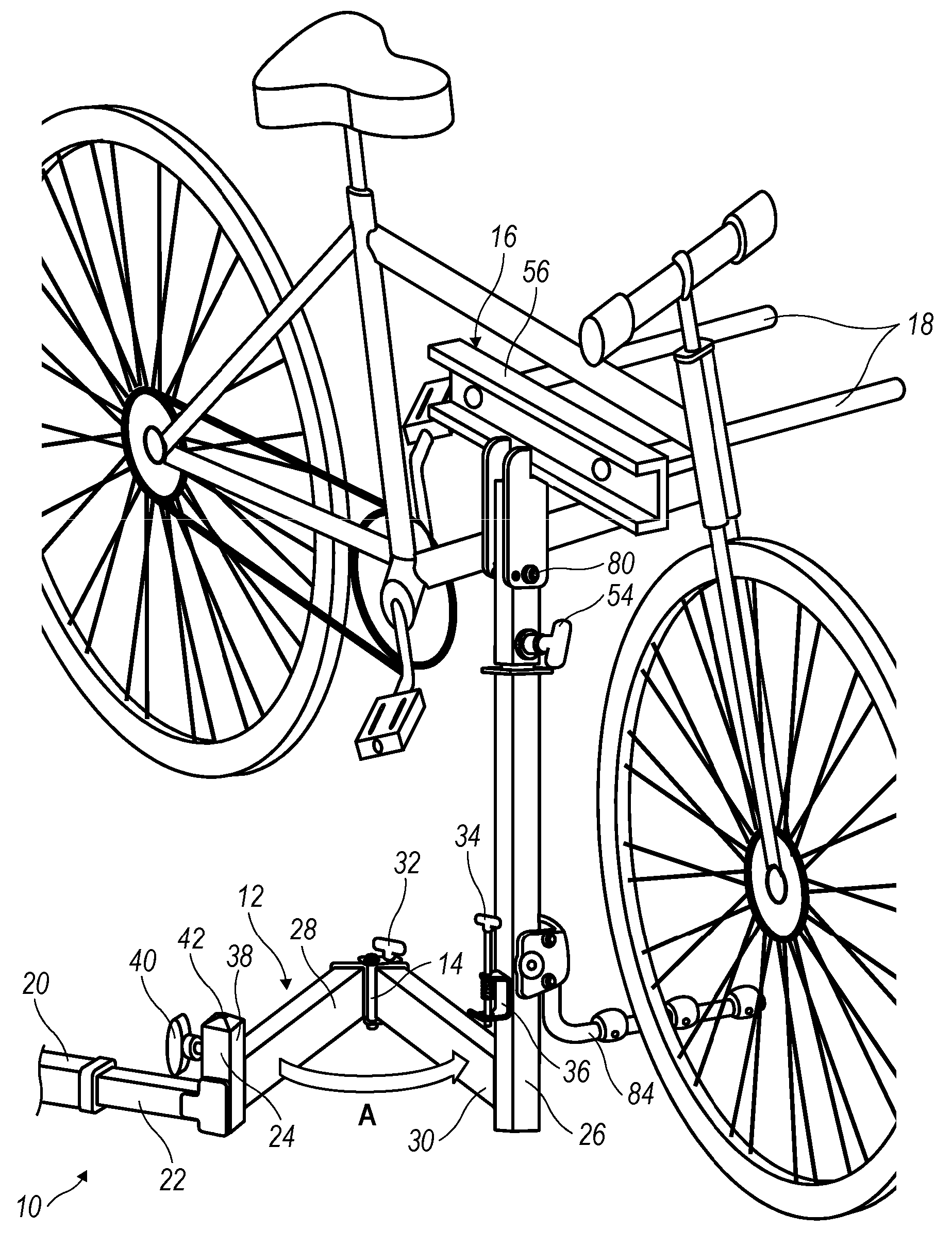
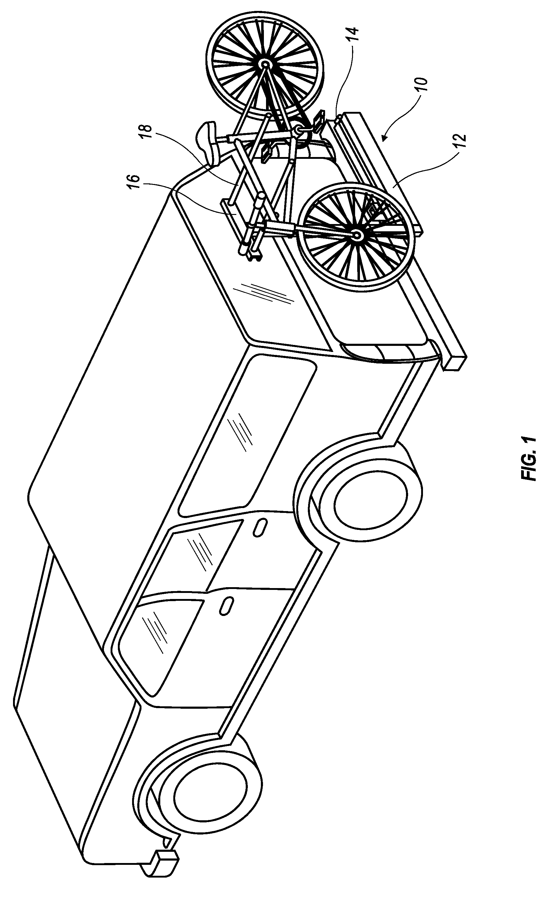
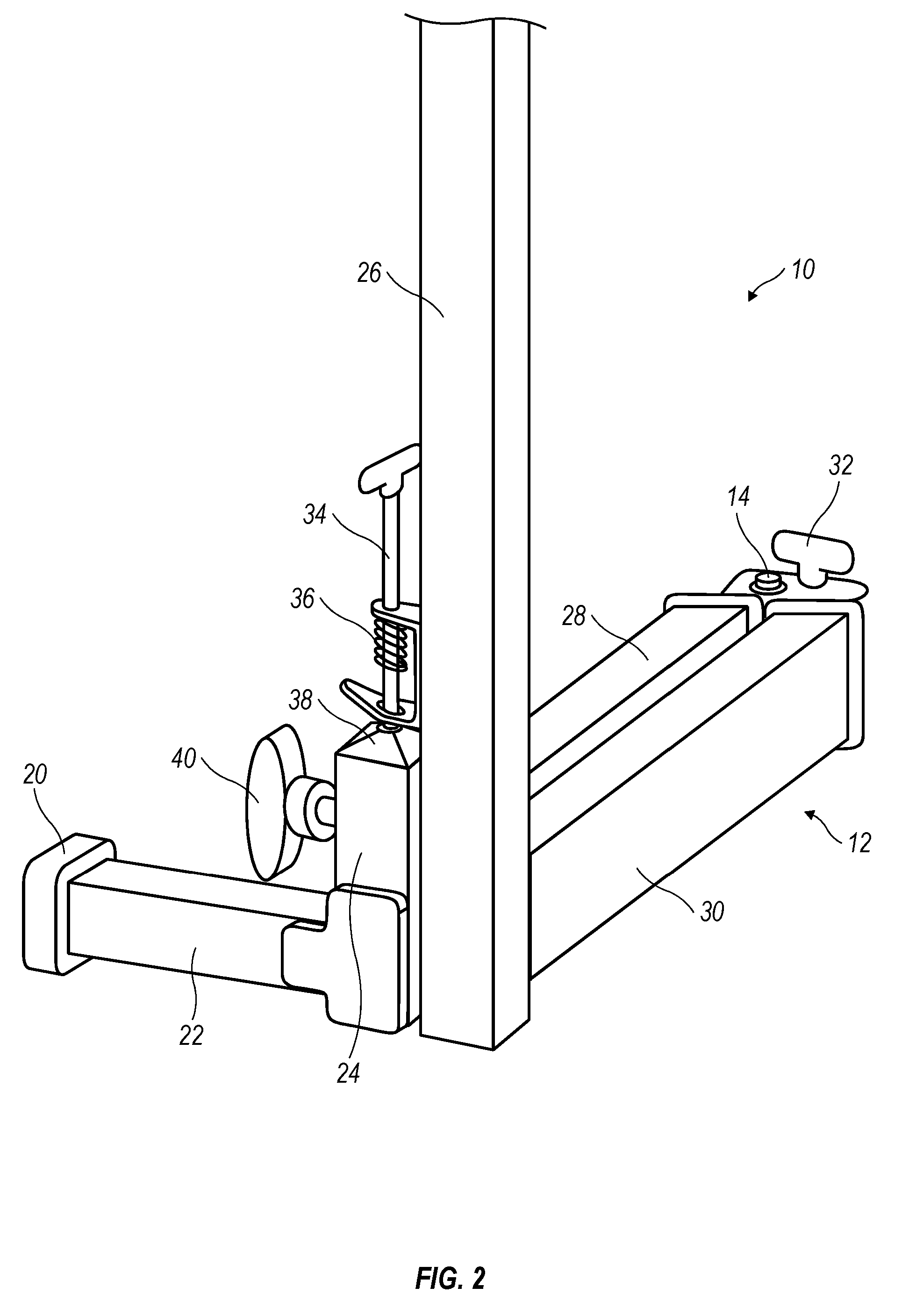
[0022] Referring now to the figures wherein like reference numerals identify like parts throughout the several views, FIG. 1 shows load carrier 10 according to the present invention used for supporting equipment, e.g., one or more bicycles, at the rear of a transporting vehicle. Load carrier 10 includes swing-away, extendable support arm 12 having pivoting...


PUM


Abstract

A vehicle mountable load carrier generally includes a connecting member for insertion into a hitch mount receiver of a vehicle, an upright post connected to the connecting member and an upright load supporting member coupled to the upright post by an extendable support arm having an open and closed positions. The extendable support arm includes at least a first section and a second section and has a pivoting coupling therebetween such that at least the second section can be moved between a closed position and an open position. The pivoting coupling includes a releasable lock to retain the extendable support arm in a locked-open position.

Description

CROSS-REFERENCE TO RELATED APPLICATIONS [0001] The present application is a continuation application of U.S. application Ser. No. 11 / 159,159 filed Jun. 23, 2005 which claims the benefit of U.S. Provisional Application Nos. 60 / 522,495 filed Oct. 6, 2004 and 60 / 582,382 filed Jun. 23, 2004. Said applications are expressly incorporated herein by reference in their entireties.FIELD OF THE INVENTION [0002] The present invention relates generally to vehicle load carriers, and more specifically, to vehicle load carrier assemblies mountable to rearward sides of vehicles. BACKGROUND OF THE INVENTION [0003] Attachment of load carriers to rearward sides of vehicles, using hitch-mount receivers, is known. Such hitch-mounted load carriers typically allow the convenient transportation of equipment, such as bicycles. One type of hitch-mounted load carrier comprises a hinged, or swing-away, type carrier. [0004] Hinged, or swing-away, type hitch mounted load carriers typically include diamond-style e...

Claims


Application Information

Patent Timeline
IPC IPC(8): B60R11/00B60R9/00
CPCB60R9/10B60R9/06
Inventor BOGOSLOFSKI, KEVINBOVE, VINCENT
Owner THULE SWEDEN AB
Why Eureka
Try Eureka