

Flowhead and method
- Summary
- Abstract
- Description
- Claims
- Application Information
AI Technical Summary
Benefits of technology
Problems solved by technology
Method used
Image

Examples
Embodiment Construction
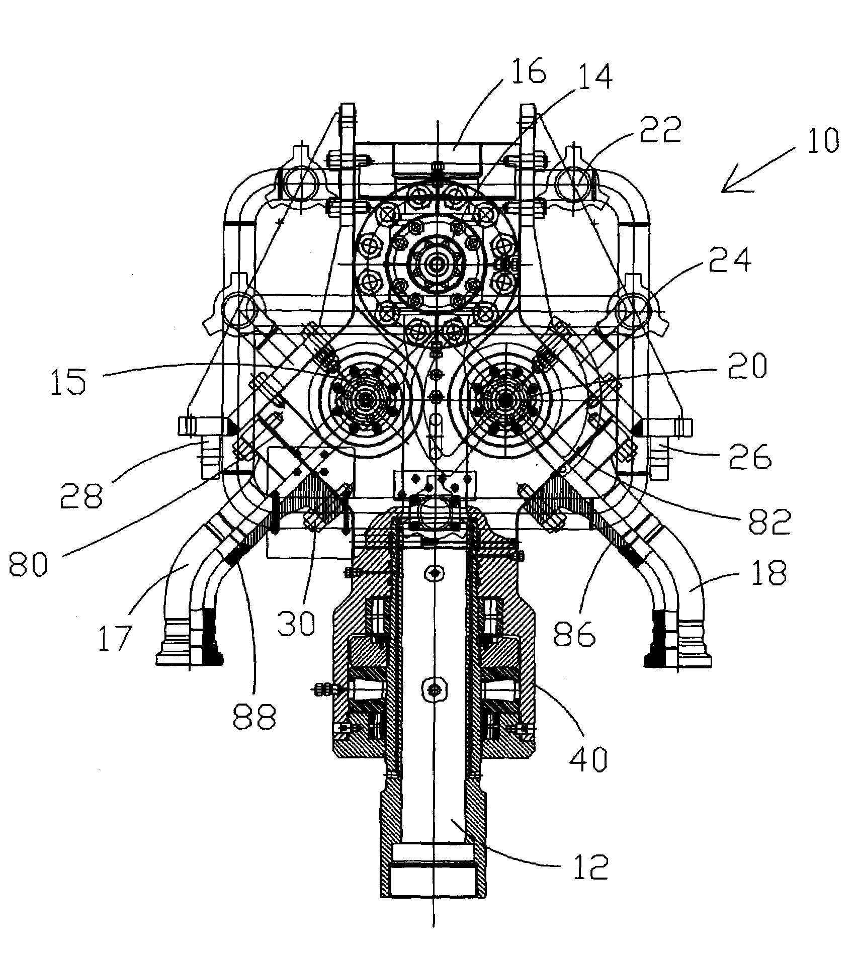
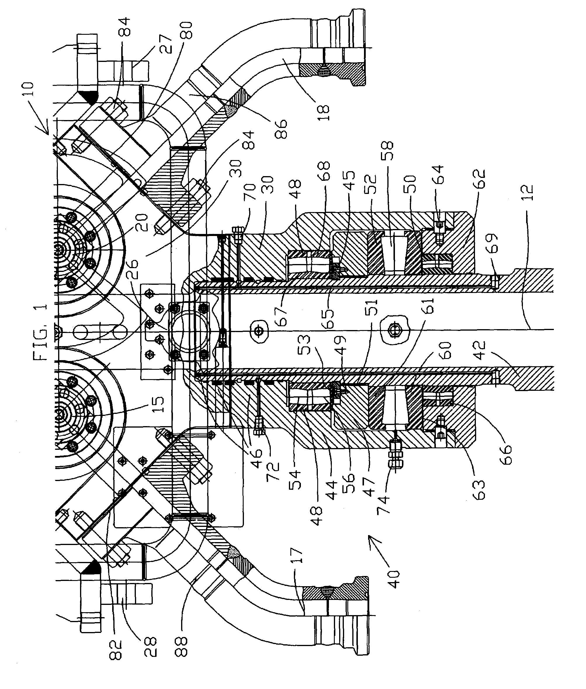
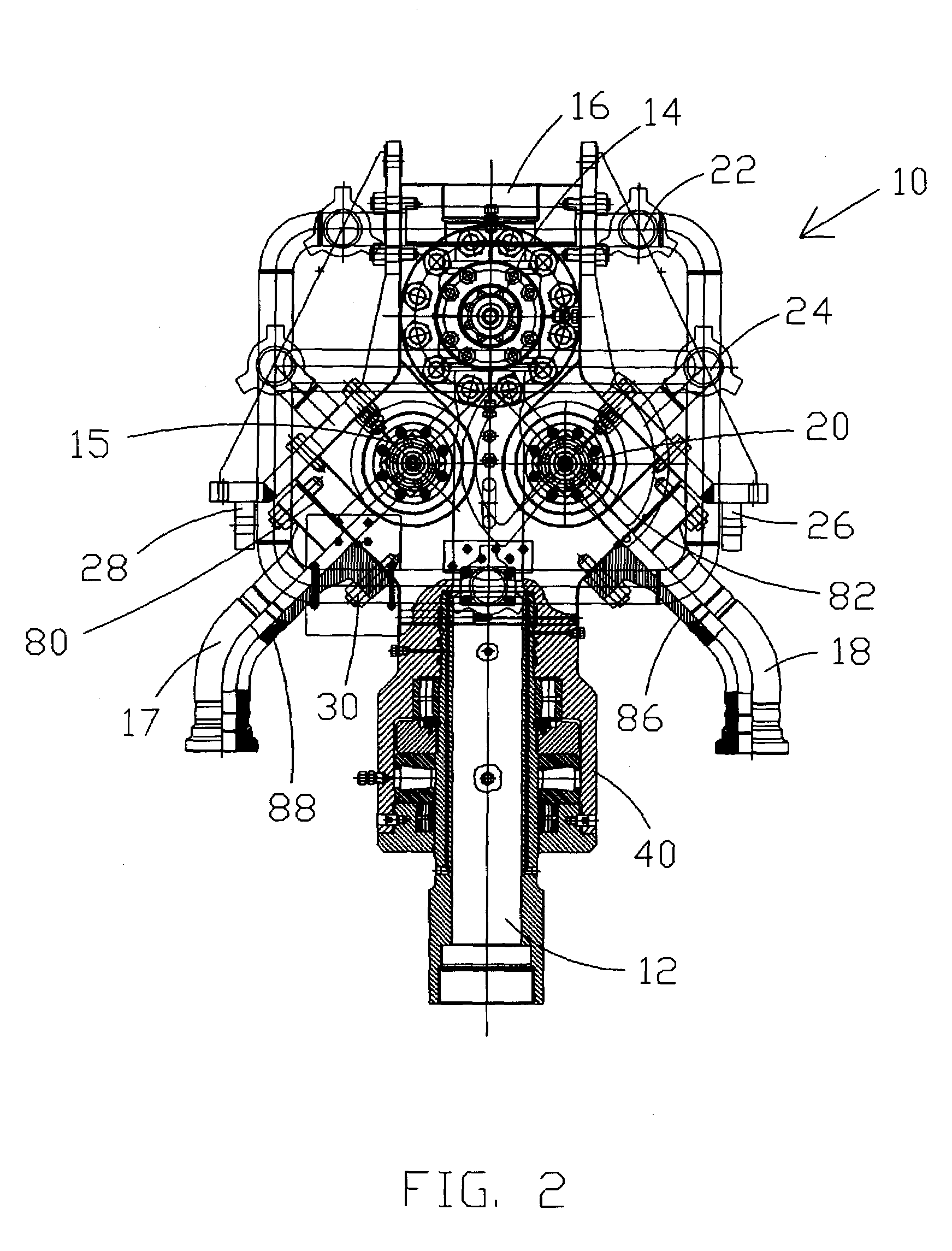
[0042]FIG. 1, FIG. 2, and FIG. 3 disclose flowhead 10 in accord with the present invention.
[0043]Referring to FIG. 4, there is shown test system 100 which utilizes flowhead 10 in accord with the present invention. Offshore drilling rig 102 may be of any type and may also comprise a drill ship or the like. Riser portion 104 of well 108 comprises numerous threaded tubulars which connect to seabed well head 106. Well 108 is further defined by threaded tubular casing 110 which extends the length of well 108. Drill pipe, or tubulars, 112, which may comprise one or more concentric strings of threaded tubulars extend from flowhead 10 on the surface to subsea well head 106. Tubular portion 114 extends to formation interval or zone 116, which is to be tested. Formation zone 116 is isolated by packers and / or plugs in manner well known to those of skill in the art so that only fluid from formation zone 116 is to be selectively flowed for testing purposes. Various valves may be located between ...
PUM
 Abstract
Description
Claims
Application Information