Device and method for positioning fixed scroll

A technology of stationary scroll and positioning device, which is applied to the combination of elastic fluid rotary piston type/oscillating piston type pump, rotary piston type pump, rotary piston type machinery, etc., to prevent rotation and improve positioning accuracy.

Inactive Publication Date: 2012-05-30
DAIKIN IND LTD
View PDF3 Cites 0 Cited by
  • Summary
  • Abstract
  • Description
  • Claims
  • Application Information

AI Technical Summary

Problems solved by technology

[0008] However, if in a state where the wrap of the fixed scroll is in contact with the wrap of the movable scroll, an impact force in a direction that increases the contact force is applied to the fixed scroll (for example, at Figure 25 In the state where the impact force is applied from the unit 70 on the right side of the figure), the impact force will exceed the friction force, then, although the rotation of the fixed scroll is restricted, the fixed scroll may still rotate
If the fixed scroll rotates, the fixed scroll cannot be positioned correctly.

Method used


Image

  • Device and method for positioning fixed scroll
  • Device and method for positioning fixed scroll
  • Device and method for positioning fixed scroll

Examples


other Embodiment approach

[0189] The following configurations can also be adopted in each of the above-described embodiments.

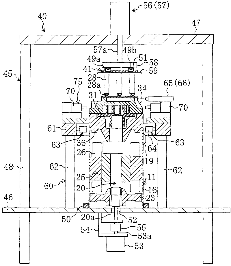
[0190] For example, in the above-described embodiment, the air cylinder unit 100 is used to advance and retreat the head portion 74 of the striking unit 70 . However, the cylinder part 100 can also be replaced by a clamping mechanism, a cam mechanism, etc.; the part that moves the fixed scroll 34, that is, the striking assembly 70 is not necessarily a structure that uses the piezoelectric element 73, and other structures can also be used, such as A moving mechanism 75 and the like of a ball screw type feeding mechanism are used. In short, as long as the moving mechanism 75 can adjust the position of the fixed scroll 34 , its structure can be appropriately changed.

[0191] In the above-described embodiment, the fixed scroll 34 is positioned while the movable scroll 31 is rotated, but it is also possible to stop the movable scroll 31 at a predetermined position and hit the fix...


PUM


Abstract

When a fixed scroll (34) is positioned by moving it in the X-axis direction and the Y-axis direction while a scroll fluid machine is assembled, the moving direction of the fixed scroll (34) is determined according to the phase of an orbiting scroll (31) to enhance the positioning accuracy by surely preventing the fixed scroll (34) from rotating. When the outer peripheral surface of a movable-sidewrap is brought into contact with the inner peripheral surface of a fixed-side wrap and the fixed scroll (34) is pushed back by the movable-side wrap when the orbiting scroll (31) is inverted after the fixed scroll (34) is moved, the portion where the outer peripheral surface of the fixed-side wrap is separated from the inner peripheral surface of the movable-side wrap (closest portion) when the fixed scroll (34) is moved is detected, as a wrap-to-wrap contact position, by a position detection mechanism (65). The position detection is performed at multiple positions to determine the center ofthe fixed scroll (34) for positioning.

Description

technical field [0001] The present invention relates to a device and method for positioning a fixed scroll when assembling a scroll fluid machine. Background technique [0002] So far, scroll fluid machines have been widely used in compressors and the like which are installed in refrigerant circuits of air conditioners and the like to compress refrigerant. In this scroll fluid machine, spiral wraps are respectively formed on the fixed scroll and the movable scroll, and a fluid chamber is formed by meshing with the wraps on the stationary side and the movable side. In this scroll fluid machine, the movable scroll orbits, and the volume of the fluid chamber changes accordingly. For example, in a scroll compressor, after fluid is sucked into the fluid chamber before the closed state, the volume of the fluid chamber that has become closed will decrease, and after the fluid in the fluid chamber is compressed, the fluid chamber that has been connected to the nozzle Fluid is ejec...

Claims


Application Information

Patent Timeline
Patent Type & Authority Patents(China)
IPC IPC(8): F04C18/02
CPCF04C2240/81F04C18/0215F04C23/008F04C2230/604F04C2230/603F04C2270/86
Inventor 广内隆诹佐利浩
Owner DAIKIN IND LTD
Why Eureka
Try Eureka