
Bandage fixing structure of medical rehabilitation training machine

A fixed structure and training machine technology, applied in the direction of passive exercise equipment, sports accessories, gymnastics equipment, etc., can solve problems such as difficulty in moving joints, troublesome binding of straps, etc., and achieve the effect of good comfort and convenient fixation

Inactive Publication Date: 2020-09-22
孙春凡
View PDF9 Cites 0 Cited by
  • Summary
  • Abstract
  • Description
  • Claims
  • Application Information

AI Technical Summary

Problems solved by technology

At present, there are many kinds of physical therapy instruments, which can treat various parts of the body. At present, there are few therapeutic instruments for the treatment of ankle joints on the market. When the functionality of the ankle joints is lost, it is necessary to rehabilitate the ankle joints. To restore the original function, but it is difficult to move the joints only by the patient himself, so someone proposes a sleeve installed on the seat, the feet can be inserted into the sleeve, and the heel rests on the bottom plate at the lower end of the sleeve The front end is designed as a pedal that can move up and down, so that the rehabilitation movement of the ankle can be moved up and down, but it is necessary to use straps to fix the legs on the sleeve, which is more troublesome

Method used


Image

  • Bandage fixing structure of medical rehabilitation training machine
  • Bandage fixing structure of medical rehabilitation training machine
  • Bandage fixing structure of medical rehabilitation training machine

Examples


Embodiment Construction

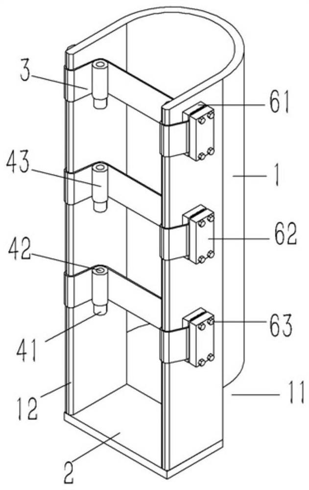
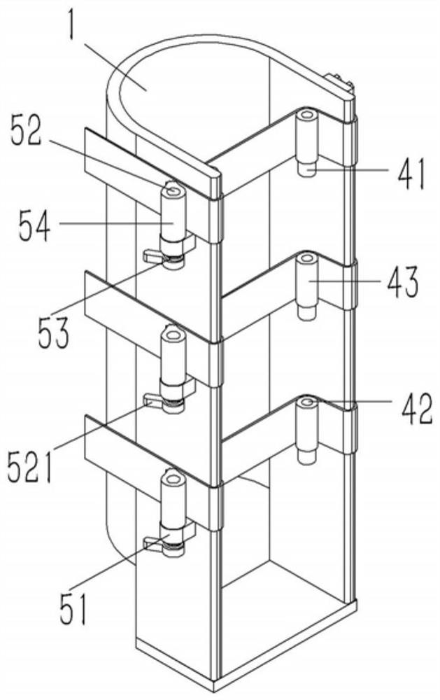
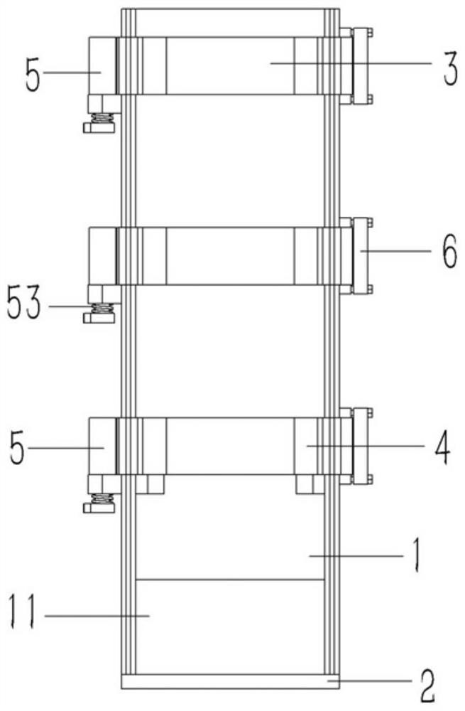
[0020] Example: see Figures 1 to 4 As shown, a strap fixing structure on a medical rehabilitation training machine includes a sleeve 1 with a U-shaped cross section, a base plate 2 is fixed at the bottom of the sleeve 1, and several sets of vertical Distributed straps 3, one end of the strap 3 is fixed on the outer wall on one side of the sleeve 1, the outer wall on the other side of the sleeve 1 is provided with a clip 5 opposite to the strap 3, the clip 5 includes a The first lug 51 on the outer wall of the seat 1, the first lug 51 is inserted with an inverted T-shaped pin 52, the upper end of the T-shaped pin 52 is exposed, and the upper end surface of the first lug 51 is inserted and fixed with a sleeve 54, the other end of the strap 3 is inserted between the bushing 54 and the outer wall of the sleeve 1, the outer wall of the bushing 54 is formed with a vertical convex strip 541, and a plurality of pressing teeth 542 are formed on the convex strip 541 , the pressing too...


PUM


Abstract

The invention discloses a bandage fixing structure of a medical rehabilitation training machine. The bandage fixing structure comprises a socket with a U-shaped cross section, wherein a bottom plate is fixed to the bottom end of the socket, a plurality of groups of vertically-distributed bandages are arranged at the front side of the socket, one end of each bandage is fixed to an external wall ofone side of the socket, fasteners opposite to the bandages are arranged on an external wall of the other side of the socket and comprise first support lugs fixed to the external wall of the socket, inverted T-shaped pin shafts are inserted into the first support lugs, upper ends of the T-shaped pin shafts expose from upper end faces of the first support lugs are in fixed sleeve joint with shaft sleeves, the other end of each bandage is inserted between one corresponding shaft sleeve and the external wall of the socket, vertical convex ribs are formed on external walls of the shaft sleeves, anda plurality of pressing teeth are formed on the convex ribs and are leant against the bandages in a pressing manner; and torsion springs sleeve the T-shaped pin shafts at lower sides of the first support lugs, one end of each torsion spring is fixed to the one corresponding first support lug, and the other end of each torsion spring is fixed to lower end of one corresponding T-shaped pin shaft.

Description

technical field [0001] The invention relates to the technical field of medical rehabilitation equipment, in particular to a strap fixing structure on a medical rehabilitation training machine. Background technique [0002] Rehabilitation, simply put, is the use of exercise, manual therapy, and different physical therapy equipment to help the recovery of sports injuries. At present, there are many kinds of physical therapy instruments, which can treat various parts of the body. At present, there are few therapeutic instruments for the treatment of ankle joints on the market. When the functionality of the ankle joints is lost, it is necessary to rehabilitate the ankle joints. To restore the original function, but it is difficult to move the joints only by the patient himself, so someone proposes a sleeve installed on the seat, the feet can be inserted into the sleeve, and the heel rests on the bottom plate at the lower end of the sleeve Up and down, the front end is designed ...

Claims


Application Information

Patent Timeline
Patent Type & Authority Applications(China)
IPC IPC(8): A61H1/02A63B23/08
CPCA61H1/0218A61H1/0237A61H2201/1642A63B23/08
Inventor 孙春凡
Owner 孙春凡
Learn More