
Camera detection jig

A technology for detecting fixtures and cameras, which is applied in the direction of manufacturing tools, workpiece clamping devices, etc., can solve problems such as inaccurate positioning, and achieve the effects of simple structure, avoiding displacement, and good positioning

Pending Publication Date: 2020-09-22
长园半导体设备(珠海)有限公司
View PDF0 Cites 0 Cited by
  • Summary
  • Abstract
  • Description
  • Claims
  • Application Information

AI Technical Summary

Problems solved by technology

During the test, the camera needs to be fixed on the jig. Since the camera body itself has shrapnel, it will be displaced during the processing, resulting in the problem of inaccurate positioning.

Method used


Image

  • Camera detection jig
  • Camera detection jig
  • Camera detection jig

Examples


Embodiment Construction

[0025] The following will clearly and completely describe the technical solutions in the embodiments of the present invention with reference to the accompanying drawings in the embodiments of the present invention. Obviously, the described embodiments are only some, not all, embodiments of the present invention. Based on the embodiments of the present invention, all other embodiments obtained by persons of ordinary skill in the art without making creative efforts belong to the protection scope of the present invention.

[0026] It should be noted that when a component is said to be “fixed” to another component, it may be directly on the other component or there may be another intermediate component through which it is fixed. When a component is said to be "connected" to another component, it may be directly connected to the other component or there may be another intermediate component at the same time. When a component is said to be "set on" another component, it may be set d...


PUM


Abstract

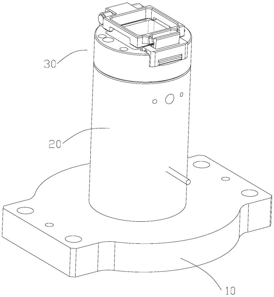
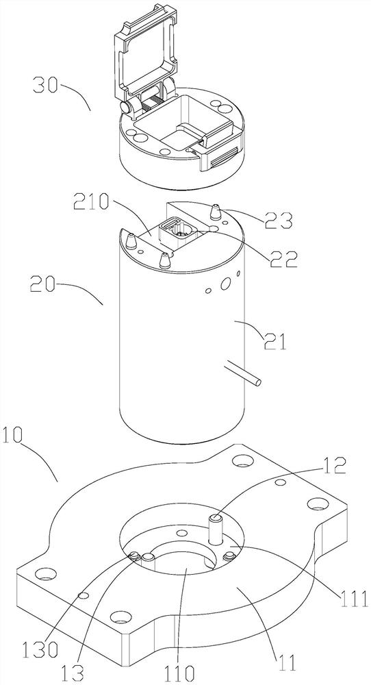
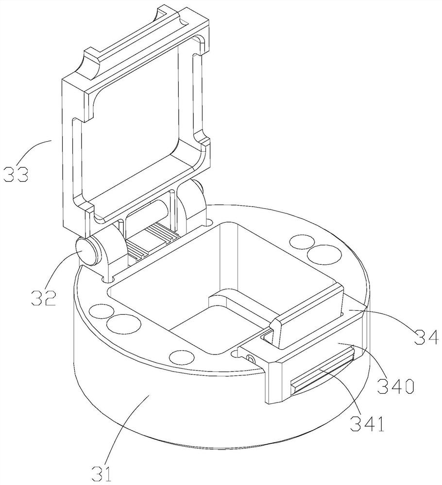
The invention discloses a camera detection jig comprising a base and an extension column. The extension column is arranged on the base, and the extension column comprises a plug. The camera detectionjig also comprises a positioning seat, the positioning seat is arranged at the end part of the extension column, the positioning seat comprises a seat body, a gland and a buckle component, the seat body is provided with an insertion hole, the plug is positioned below the insertion hole, the gland is provided with an opening and a buckle groove, the gland is rotatably arranged on the seat body, thebuckle component comprises a buckle part, the buckle part is rotatably arranged on the seat body and is elastically connected with the seat body, the buckle part comprises a buckle portion, and the buckle portion and the buckle groove are buckled to enable the gland to be fixed on the seat body; through the design, the structure is simple, and a camera can be placed rapidly; the stability and thepositioning performance are good, and the displacement of the camera during installation is avoided; and the extension column is adjustable in height and can be applied to detection of positions withdifferent heights.

Description

technical field [0001] The invention relates to a detection jig, in particular to a camera detection jig. Background technique [0002] After the camera is manufactured, it can only leave the factory after the performance is tested by the integrating sphere. During the test, the camera needs to be fixed on the jig. Since the camera body itself has shrapnel, it will be displaced during the processing process, resulting in the problem of inaccurate positioning. Contents of the invention [0003] In order to overcome the deficiencies of the prior art, one of the objectives of the present invention is to provide a camera inspection jig capable of accurately positioning the camera during inspection. [0004] One of purpose of the present invention adopts following technical scheme to realize: [0005] A camera detection jig, comprising a base and an extension column, the extension column is installed on the base, the extension column includes a plug, the camera detection jig ...

Claims


Application Information

Patent Timeline
Patent Type & Authority Applications(China)
IPC IPC(8): B25B11/00
CPCB25B11/00
Inventor 侯峰陈庆龙
Owner 长园半导体设备(珠海)有限公司
Learn More