Supporting frame with locating function

a technology of supporting frame and function, which is applied in the direction of machines/engines, liquid fuel engines, light and heating apparatus, etc., can solve the problems of high die-cutting cost and manufacturing of conventional supporting frame, and achieve the effects of convenient assembly, rapid positioning in place, and reduced cos

Active Publication Date: 2005-12-08
ASIA VITAL COMPONENTS SHENZHEN CO LTD
View PDF12 Cites 25 Cited by
  • Summary
  • Abstract
  • Description
  • Claims
  • Application Information

AI Technical Summary

Benefits of technology

[0010] A primary object of the present invention is to provide a supporting frame that can be conveniently assembled.
[0011] Another object the present invention is to provide a supporting frame that can be manufactured at reduced cost.
[0012] A ...

Problems solved by technology

A highly expensive die-cutting cost is required ...

Method used


Image

  • Supporting frame with locating function
  • Supporting frame with locating function
  • Supporting frame with locating function

Examples


first embodiment

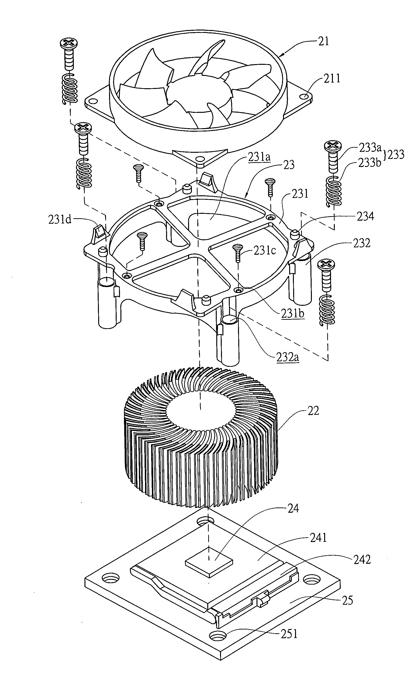
[0024] Please refer to FIGS. 4 and 5 in which a supporting frame with locating function according to a first preferred embodiment of the present invention is shown. As shown, the supporting frame in the first embodiment is generally denoted with a reference numeral 23 and substantially in the form of an annular ring for use over a round-shaped radiator 22. The supporting frame 23 mainly includes a supporting portion 231 and a plurality of connecting portions 232. The supporting portion 231 is provided at a central area with a plurality of hollow spaces 231a, at a rim area with spaced and upward extended locating rods 234 for engaging with receiving holes 211 formed on a fan 21, which is to be located above the supporting frame 23, and also at the rim area with spaced fixing holes 231b, through which fastening elements 231c are extended to thereby connect the supporting portion 231 to a radiator 22 with a lower side of the supporting portion 231 closely bearing against a top of the r...

second embodiment

[0027] Please refer to FIGS. 6 and 7 in which a supporting frame with locating function according to a second preferred embodiment of the present invention is shown. As shown, the supporting frame in the second embodiment is generally denoted with a reference numeral 27 and substantially in the form of a polygonal support for use over a polygonal radiator 28. The supporting frame 27 mainly includes a supporting portion 271 and a plurality of connecting portions 272. The supporting portion 271 is provided at a central area with a plurality of hollow spaces 271a, at a rim area with spaced and upward extended locating rods 274 for engaging with receiving holes 261 formed on a fan 26, which is to be located above the supporting frame 27, and also at the rim area with spaced fixing holes 271b, through which fastening elements 271c are extended to thereby connect the supporting portion 271 to a radiator 28 with a lower side of the supporting portion 271 closely bearing against a top of th...


PUM


Abstract

A supporting frame with locating function mainly includes a supporting portion and a plurality of connecting portions. The supporting portion is provided at a central area with a plurality of hollow spaces, and is connected at an upper side to a fan and at a lower side to a radiator. The supporting portion is provided on a rim area with fixing holes, via which fastening elements are extended to connect the supporting portion to the radiator. Each of the connecting portions includes an axially extended connecting hole, in which a locating mechanism is received. The connecting portion is connected at an upper side to the supporting portion, and at a lower side to a main board via screwing and elastic elements of the locating mechanism. With the supporting frame, the fan and the radiator can be quickly assembled to the main board.

Description

FIELD OF THE INVENTION [0001] The present invention relates to a supporting frame with locating function in connection with a central processing unit (CPU), and more particularly to a supporting frame with locating function for locating a fan and a radiator above a CPU to enable good radiating of heat produced by the CPU during operation thereof. BACKGROUND OF THE INVENTION [0002]FIG. 1 shows a conventional supporting frame 13 mainly including a main body 131 and a plurality of locating mechanisms 132. The main body 131 includes a central area that is in contact with a CPU 14 to transfer heat produced by the CPU 14 during operation thereof to a radiator 12 connected to a top of the main body 131. The main body 131 and the radiator 12 are connected together by means of welding, bonding, or mechanical engagement. The locating mechanism 132 includes a driving element 132a and a driven element 132b, into which the driving element 132a is inserted. When the driving element 132a is depres...

Claims


Application Information

Patent Timeline
IPC IPC(8): F04D29/58F04D29/60F01D5/08
CPCF04D29/582F04D29/601
Inventor PAN, MING-HUI
Owner ASIA VITAL COMPONENTS SHENZHEN CO LTD
Why Eureka
Try Eureka