
Exposure machine adjusting method and device

An adjustment method and technology of an exposure machine, which are applied to exposure devices in photo-engraving process, optomechanical equipment, microlithography exposure equipment, etc., can solve problems such as affecting the quality of exposure imaging, manual installation errors, not necessarily completely parallel, etc., to avoid The effect of uneven exposure imaging and improved quality

Active Publication Date: 2020-09-22
BOE TECH GRP CO LTD +1
View PDF4 Cites 3 Cited by
  • Summary
  • Abstract
  • Description
  • Claims
  • Application Information

AI Technical Summary

Benefits of technology

The technical effect of this patented technology allows for precise control over how much light falls onto different parts of an image being exposed during lithography processes. This helps improve the accuracy and consistency with other manufacturing steps such as etchings or printing patterns.

Problems solved by technology

The technical problem addressed in this patented text relates to improving image resolution when creating patterns for devices with digital microscope mirror devices used during production processes. This can be caused because there may have issues with achieving accurate alignment between the two components while they work together accurately or even if some parts were misaligned before assembly.

Method used


Image

  • Exposure machine adjusting method and device
  • Exposure machine adjusting method and device
  • Exposure machine adjusting method and device

Examples


Embodiment 1

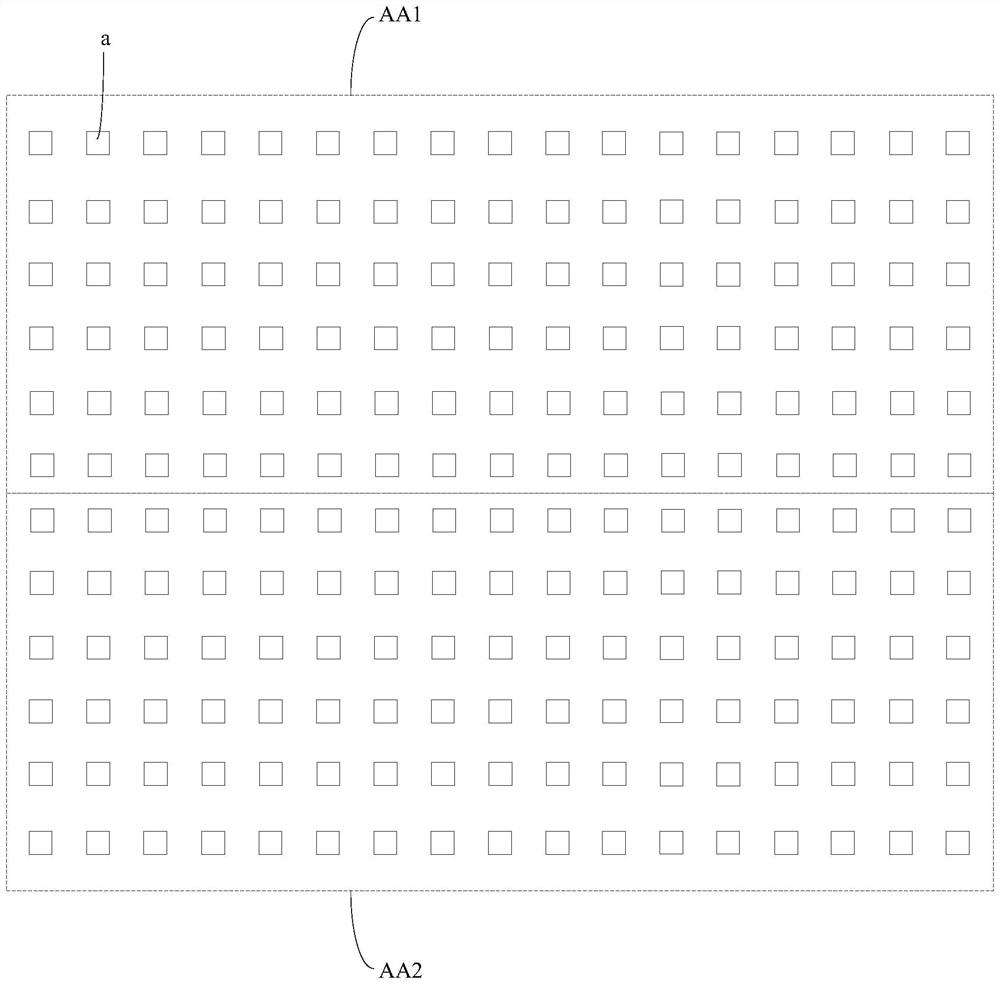
[0069] During specific implementation, the exposure machine in the embodiment of the present invention may be an LDI exposure machine. Generally, the scanning exposure process of the LDI exposure machine is: control the movement of the platform used to carry the substrate in the exposure machine, and feed back the position signal to the data processing module while the platform is moving. The data processing module generates the position signal according to the position signal fed back by the platform. The image is projected on the DMD, and the DMD reflects the light beam to the substrate to complete the exposure work at this position. combine Figure 1b As mentioned above, in this manner, one scanning exposure can form a striped scanning band, that is, the first scanning exposure can form a striped scanning band AA1, and the second scanning exposure can form a striped scanning band AA2. In addition, there may be a plurality of exposure areas a in the strips AA1 and AA2. Aft...

Embodiment 2

[0113] This embodiment is a modification of some of the implementation manners in the first embodiment. The following only describes the differences between this embodiment and the first embodiment, and the similarities will not be repeated here.

[0114] In specific implementation, in the embodiment of the present invention, an exposure machine is used to expose multiple preset regions of the photoresist, which may specifically include:

[0115] Control the exposure machine to perform a scanning exposure to expose the two rows of preset areas corresponding to the photoresist in the third scanning area; wherein, the first row of the two rows of preset areas in the third scanning area is close to the first row The upper boundary of the third scan area, the second row is close to the lower boundary of the third scan area. In this way, only one exposure can be used, thereby reducing power consumption. Taking N=17 as an example, combine Figure 7 As shown, a row of preset areas...


PUM


Abstract

The invention discloses an exposure machine adjusting method and device, and the method comprises the steps: carrying out the patterning of a plurality of preset regions currently selected by photoresist on a substrate, and enabling the photoresist to generate a plurality of patterned preset regions; determining a preset area with a complete graph in two rows of preset areas after graphical processing, and determining target distances corresponding to the selected two rows of preset areas according to a preset exposure distance corresponding to the selected preset area with the complete graphin each row. In this way, when it is determined that the difference between the target distances corresponding to the two rows of preset areas does not meet the preset threshold range, it is indicatedthat the DMD is not completely parallel to the plane where the substrate is located, and the angle of the digital micromirror device in the laser head can be adjusted according to the difference between the target distances. According to the invention, a plurality of preset areas can be reselected for patterning, and the target distances corresponding to the two selected rows of preset areas aredetermined until the difference between the target distances meets the preset threshold range, so as to ensure that the DMD is completely parallel to the plane where the substrate is located as much as possible.

Description


Claims


Application Information

Patent Timeline
Owner BOE TECH GRP CO LTD
Learn More