Electric power iron tower high-voltage line pre-tightening device

A technology for power towers and high-voltage lines is applied in the field of high-voltage line laying equipment, which can solve the problems of high risk, damage to the outer wall of the cable, and reduce the practical life of the cable, so as to improve safety and convenience, facilitate high-altitude operations, and avoid stretching. oversized effect

Active Publication Date: 2020-09-22
STATE GRID HEBEI ELECTRIC POWER CO LTD +1
View PDF4 Cites 1 Cited by
  • Summary
  • Abstract
  • Description
  • Claims
  • Application Information

AI Technical Summary

Problems solved by technology

[0002] With the laying of electricity, in order to meet more regional electricity consumption, the laying length of high-voltage cables is getting longer and longer. However, due to the high building height of high-voltage cables, there are more problems in the laying of high-voltage cables.
[0003] Since the laying of high-voltage cables is a high-altitude operation, it takes a lot of manpower to stretch the high-voltage cables. At the same time, human pulling is dangerous, which is not conducive to the operation of high-altitude laying. At the same time, the high-voltage cables are pre-tensioned. The common pre-tensioning device is motor rotation and winding. However, because the winding of the motor is difficult to achieve precise control, it is very easy to cause excessive pre-tension stretching, causing damage to the outer wall of the cable or breaking the cable, thereby reducing the practical life of the cable.
[0004] To this end, a pretensioning device for high-voltage wires of electric power towers is provided to solve the problems of automatic tensioning and pretensioning adjustment of cables

Method used


Image

  • Electric power iron tower high-voltage line pre-tightening device
  • Electric power iron tower high-voltage line pre-tightening device
  • Electric power iron tower high-voltage line pre-tightening device

Examples


Embodiment Construction

[0027] The following will clearly and completely describe the technical solutions in the embodiments of the present invention with reference to the accompanying drawings in the embodiments of the present invention. Obviously, the described embodiments are only some, not all, embodiments of the present invention. Based on the embodiments of the present invention, all other embodiments obtained by persons of ordinary skill in the art without making creative efforts belong to the protection scope of the present invention.

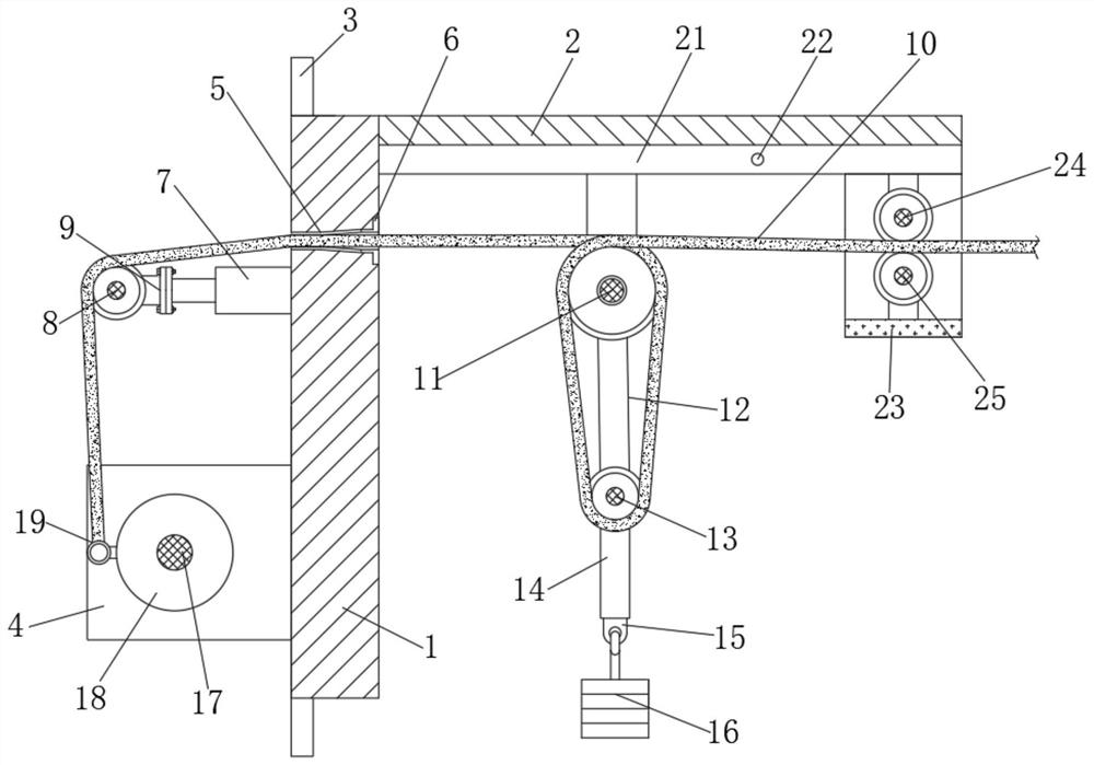
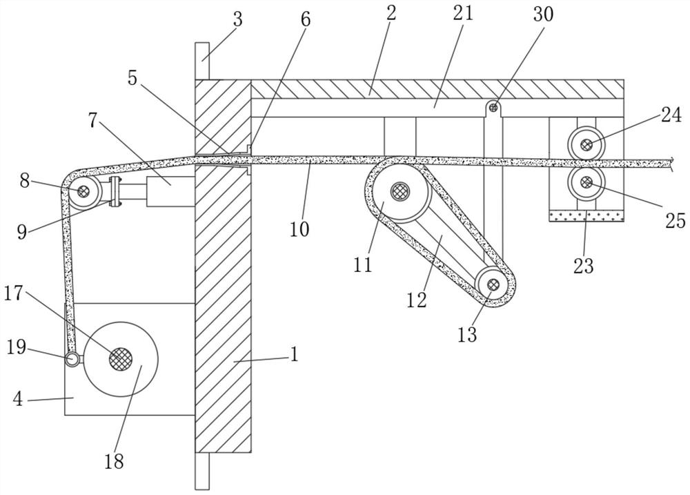
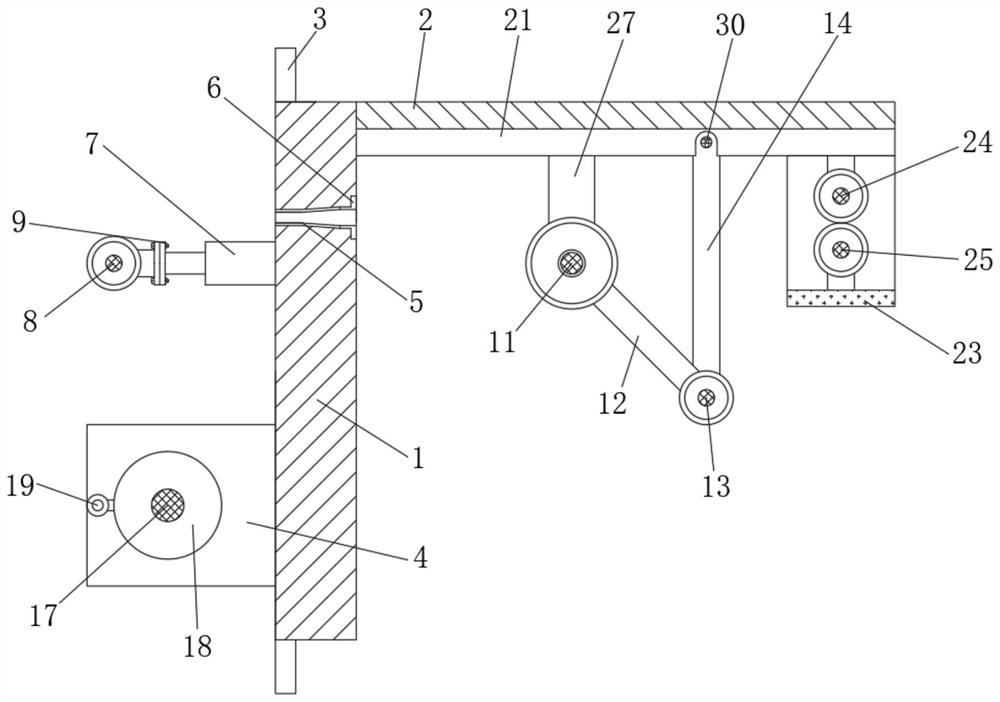
[0028] see Figure 1 to Figure 6 , the present invention provides a technical solution:

[0029] A pretensioning device for a high-voltage line of an electric power tower, comprising a vertical plate 1, the upper end of the right side of the vertical plate 1 is transversely welded with a beam plate 2, the vertical plate 1 is vertically attached to the upper side of the electric tower, and the vertical plate 1 The upper and lower ends are provided with a pair ...


PUM


Abstract

The invention relates to the technical field of a high-voltage line laying device and particularly relates to an electric power iron tower high-voltage line pre-tightening device. The high-voltage line pre-tightening device of an electric power iron tower comprises a vertical plate, wherein a cross beam plate is transversely welded at an upper end of the right side of the vertical plate, a throughhole penetrating left and right is formed in an upper end of the vertical plate, and an electric telescopic rod and a side support are vertically welded at upper and lower ends of the left side of the vertical plate. The high-voltage line laying device is advantaged in that winding and fixing of a high-voltage cable are achieved through cooperation of a driving motor and a pulley, so stretching and laying of the high-voltage cable are achieved through rotation of a motor, manual pulling is avoided, operation safety and convenience are greatly improved, and high-altitude operation is more convenient, three-stage pre-tightening is realized through motor driving, extension of a telescopic rod and stretching of a balancing weight, so adjustment of pre-tightening force is refined, the magnitude of the pre-tightening force on the high-voltage cable is convenient to control, excessive stretching is avoided, and a purpose of fine adjustment is realized.

Description

technical field [0001] The invention relates to the technical field of high-voltage line laying equipment, in particular to a high-voltage line pretensioning device for an electric power tower. Background technique [0002] With the laying of electricity, in order to meet more regional electricity consumption, the laying length of high-voltage cables is getting longer and longer. However, due to the high building height of high-voltage cables, there are many problems in the laying of high-voltage cables. [0003] Since the laying of high-voltage cables is a high-altitude operation, it takes a lot of manpower to stretch the high-voltage cables. At the same time, human pulling is dangerous, which is not conducive to the operation of high-altitude laying. At the same time, the high-voltage cables are pre-tensioned. The common pretensioning device is motor rotation winding. However, because the winding of the motor is difficult to achieve precise control, it is very easy to caus...

Claims


Application Information

Patent Timeline
Patent Type & Authority Applications(China)
IPC IPC(8): H02G1/04
CPCH02G1/04
Inventor 卢毅伟
Owner STATE GRID HEBEI ELECTRIC POWER CO LTD
Why Eureka
Try Eureka