Lens module and camera
A lens module and camera technology, applied in image communication, TV, color TV components and other directions, can solve the problems of time-consuming position adjustment, difficulty in adjusting the position of the lens, poor user experience, etc., and meet the requirements of reducing installation accuracy. , The effect of low installation position accuracy requirements and convenient installation of cameras
- Summary
- Abstract
- Description
- Claims
- Application Information
AI Technical Summary
Problems solved by technology
Method used
Image

Examples
Embodiment 1
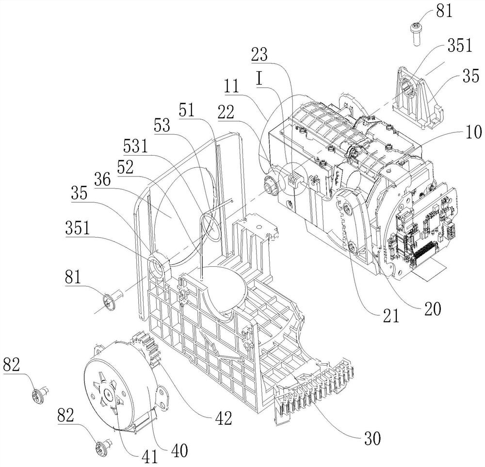
[0049] Such as Figure 1-Figure 6 As shown, this embodiment discloses a lens module 100, the above-mentioned lens module 100 includes a lens assembly 10, a first mount 20, a second mount 30 and a first drive assembly 40, the lens assembly 10 includes a lens 11 . The lens assembly 10 is connected to the first mount 20 . The first mounting frame 20 is rotatably connected with the second mounting frame 30 , and the second mounting frame 30 is used for connecting with the casing of the camera 200 . The first driving assembly 40 drives the first installation frame 20 to rotate.
[0050] The advantage of the lens module 100 of this embodiment is that: the first mounting frame 20 of this embodiment can rotate under the driving of the first driving assembly 40, and the lens assembly 10 rotates with the rotation of the first mounting frame 20, that is, the present embodiment The position of the lens 11 of the lens module 100 of the example is adjustable, so that after the lens module ...
Embodiment 2
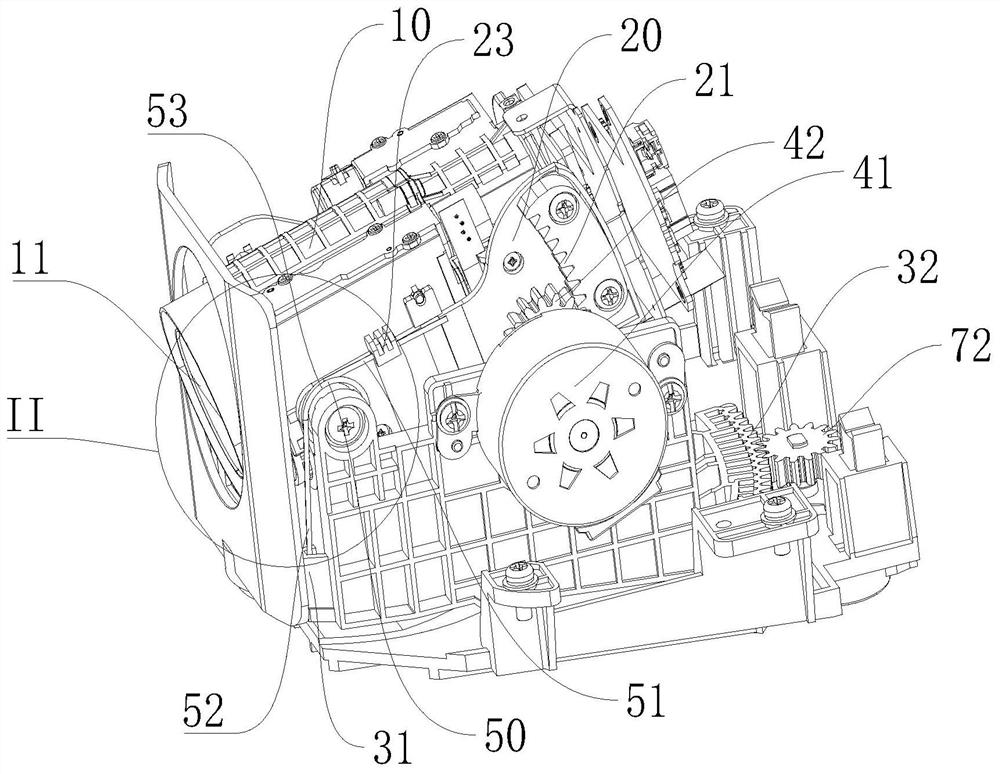
[0063] Such as Figure 1-15 As shown, the lens module 100 of this embodiment includes the lens module 100 of Embodiment 1, the lens module 100 of this embodiment also includes a third mounting frame 60 and a second driving assembly 70, and the first driving assembly 40 drives the second driving assembly 70. A mounting frame 20 rotates on the first plane, the second mounting frame 30 is rotatably connected to the third mounting frame 60 , and the second driving assembly 70 drives the second mounting frame 30 to rotate on the second plane. The first plane is perpendicular to the second plane. For example: after the lens module 100 is installed on the camera, the first plane may be a plane perpendicular to the ground, and the second plane may be a plane horizontal to the ground.
[0064] Such as Figure 10 As shown, the second mounting frame 30 is provided with a second rotating shaft 37 on the surface facing the third mounting frame 60. Correspondingly, the third mounting fram...
Embodiment 3
[0076] Such as Figure 16 As shown, this embodiment discloses a camera 200, the camera 200 includes a first housing 210 and the lens module 100 of Embodiment 2, the first housing 210 has an installation cavity, and the first housing 210 is provided with The first viewing window 211 , the lens module 100 is disposed in the installation cavity of the first housing 210 , and the lens 11 is disposed opposite to the first viewing window 221 .
[0077] Both the first power part 41 and the second power part 71 of this embodiment can be connected to the control circuit board of the camera 200 for signals, and the camera 200 can be provided with an angle adjustment button or a knob to control the rotation of the lens 11.
[0078] The advantage of the camera 200 of this embodiment is that: the first mounting frame 20 can rotate under the drive of the first drive assembly 40, and the lens assembly 10 rotates with the rotation of the first mounting frame 20, that is, the lens module 100 o...
PUM
| Property | Measurement | Unit |
|---|---|---|
| Rotation angle | aaaaa | aaaaa |
Abstract
Description
Claims
Application Information
PatSnap Eureka turns technology decisions into work you can execute. Powered by our Innovation Knowledge Graph, it runs expert workflows across engineering, life sciences, materials and intellectual property. Get your review-ready output in minutes.


