

Gear and rack floating clearance transmission device and gear and rack transmission device
A technology of rack and pinion, transmission device, applied in the direction of transmission device, friction transmission device, electromechanical device, etc., can solve the problems of increased wear of gear and rack, thankless, affecting economic benefits, etc., to reduce the installation accuracy. requirements, reduce the requirements of machining accuracy, and improve the effect of adaptability
- Summary
- Abstract
- Description
- Claims
- Application Information
AI Technical Summary
Problems solved by technology
Method used
Image

Examples
Embodiment Construction
[0027] The preferred embodiments of the present invention will be described in detail below in conjunction with the accompanying drawings, and the present invention will be further elaborated.
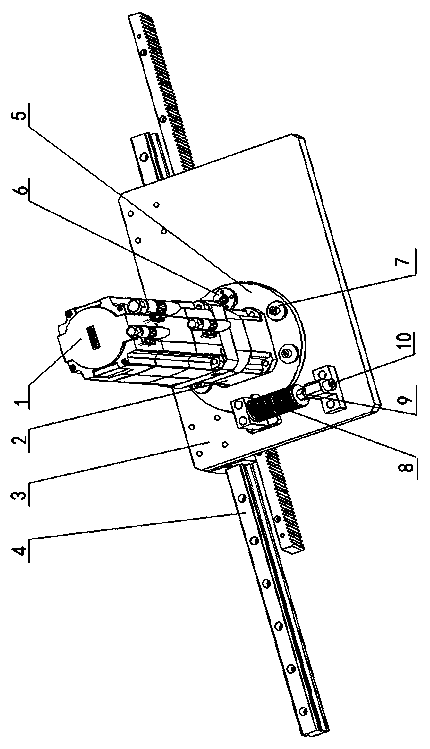
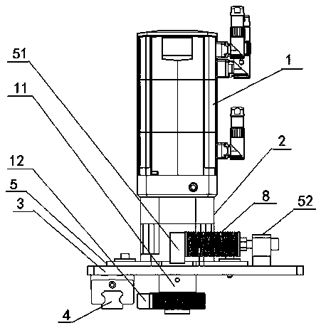
[0028] First, combine the Figure 1~2 Description The rack-and-pinion floating anti-backlash transmission device according to the embodiment of the present invention can be used in a large number of rack-and-pinion automatic transmission facilities, and is mainly suitable for straight or large-arc transmission tracks, and has extremely wide application scenarios.
[0029] Such as Figure 1~2 As shown, the rack and pinion floating anti-backlash transmission device of the embodiment of the present invention is used in rack and pinion transmission facilities. The transmission track of the guide device is a straight line or a large arc. Anti-backlash module.
[0030] Specifically, such as Figure 1~2 As shown, the support module is fixed on the slider of the guide device. In this embodi...
PUM
 Abstract
Description
Claims
Application Information