
Micro approximate U-shaped scraper clamping plate regulating mechanism

An adjustment mechanism and scraper technology, applied in the field of coating machines, can solve problems such as poor straightness accuracy, simple structure, and poor quality of coated products, and achieve the effect of reducing processing accuracy, simple and ingenious structure, and stable and reliable quality

Pending Publication Date: 2017-10-10
ZHONGSHAN SONGDE NEW MATERIAL EQUIP CO LTD
View PDF13 Cites 1 Cited by
  • Summary
  • Abstract
  • Description
  • Claims
  • Application Information

AI Technical Summary

Problems solved by technology

[0002] The straightness of the micro-concave scraper splint on the existing micro-gravure coating head is usually not fine-tuned, and the straightness of the scraper splint is guaranteed solely by the machining accuracy of the scraper splint; The manufacturing cost of the scraper splint remains high. Even so, the internal stress of the processed scraper splint is difficult to completely eliminate. After a period of use, as the internal stress is slowly released, the scraper splint will be deformed. At this time, the accuracy of the straightness is low. It will become worse, so that the quality of the product obtained by coating is poor, which cannot meet the quality requirements of customers. There are also adjustments through the threaded pair of straight jacks or by sliding between two sliders with inclined surfaces. The former has a simple structure and is easy for customers to adjust. Normal production cannot be carried out, and the above technical problems cannot be solved well

Method used


Image

  • Micro approximate U-shaped scraper clamping plate regulating mechanism
  • Micro approximate U-shaped scraper clamping plate regulating mechanism

Examples


Embodiment Construction

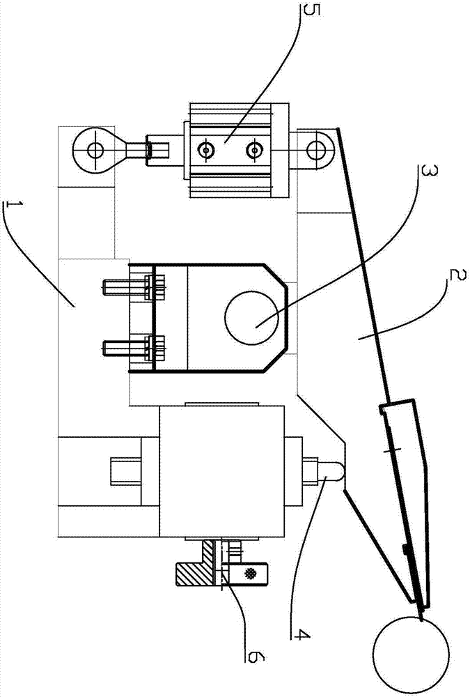
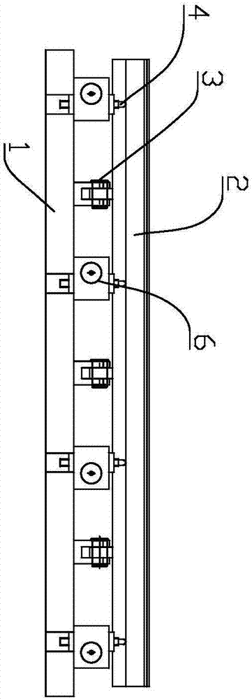
[0019] refer to Figure 1 ~ Figure 2 , the present invention is a dimple scraper splint adjustment mechanism, comprising:

[0020] mount 1;

[0021] The scraper splint 2 is pivotally connected to the mounting base 1 through a pivot 3 in the middle;

[0022] A plurality of adjusting rods 4 are installed on the mounting base 1 and located on one side of the pivot 3, and each adjusting rod 4 can be independently raised and lowered relative to the mounting base 1;

[0023] The force applying device 5 is installed on the mounting base 1 , and the force applying device 5 is used to drive the scraper splint 2 to always be in contact with the adjusting rod 4 .

[0024] The present invention can adjust the height of the adjustment rod 4 according to the straightness of the scraper splint 2, and then the scraper splint 2 is pressed against the adjustment rod 4 by the force applying device 5 to realize the correction of the straightness of the scraper splint 2 and reduce the processing...


PUM


Abstract

The invention discloses a micro approximate U-shaped scraper clamping plate regulating mechanism. The micro approximate U-shaped scraper clamping plate regulating mechanism comprises a mounting base, a scraper clamping plate, a plurality of regulating rods, and a force applying device, wherein the middle part of the scraper clamping plate is pivoted on the mounting base through a pivotal shaft; the regulating rods are mounted on the mounting base, and are positioned at one side of the pivotal shaft; each regulating rod can independently lift relative to the mounting base; and the force applying device is mounted on the mounting base and is used for driving the scraper clamping plate to be in contact with the regulating rods all the time. The micro approximate U-shaped scraper clamping plate regulating mechanism disclosed by the invention can regulate height of the regulating rods according to straightness of the scraper clamping plate, and the force applying device is used for enabling the scraper clamping plate to abut against the regulating rods to realize correcting straightness of the scraper clamping plate, so that requirements on processing precision of the scraper clamping plate are reduced; even straightness of the scraper plate changes again in a using process, straightness of the scraper clamping plate also can be regulated by regulating height of the regulating rods, so that quality of products produced within the whole coating period is excellent, and quality is stable and reliable. The micro approximate U-shaped scraper clamping plate regulating mechanism is simple and delicate in structure, and is very practical.

Description

technical field [0001] The invention relates to the field of coating machines, in particular to a dimple scraper splint adjustment mechanism. Background technique [0002] The straightness of the micro-concave scraper splint on the existing micro-gravure coating head is usually not fine-tuned, and the straightness of the scraper splint is guaranteed solely by the machining accuracy of the scraper splint; The manufacturing cost of the scraper splint remains high. Even so, the internal stress of the processed scraper splint is difficult to completely eliminate. After a period of use, as the internal stress is slowly released, the scraper splint will be deformed. At this time, the accuracy of the straightness is low. It will become worse, so that the quality of the product obtained by coating is poor, which cannot meet the quality requirements of customers. There are also adjustments through the threaded pair of straight jacks or by sliding between two sliders with inclined sur...

Claims


Application Information

Patent Timeline
IPC IPC(8): B05C1/08
CPCB05C1/0817
Inventor 张晓玲郭晓春甘德韶谢起峰方志远
Owner ZHONGSHAN SONGDE NEW MATERIAL EQUIP CO LTD
Learn More