Medium thickness detection device and method

A medium thickness and detection device technology, which is applied to the authenticity inspection of banknotes, handling coins or valuable banknotes, instruments, etc., can solve the problems of error, cost increase, and not strictly equal radii, etc., to reduce processing costs and reduce processing costs. Accuracy requirements, the effect of improving detection accuracy

Active Publication Date: 2016-11-02
SHENZHEN YIHUA COMP +2
View PDF6 Cites 1 Cited by
  • Summary
  • Abstract
  • Description
  • Claims
  • Application Information

AI Technical Summary

Problems solved by technology

[0004] The purpose of the present invention is to provide a medium thickness detection device and method, aiming to solve the problem that the radius of the driving shaft in the traditional thickness

Method used


Image

  • Medium thickness detection device and method
  • Medium thickness detection device and method
  • Medium thickness detection device and method

Examples


Embodiment 1

[0018] The first embodiment of the present invention provides a medium thickness detection device. The medium thickness detecting device can be applied to banknote checking modules of automatic cash machines and other financial automatic equipment to detect the thickness of banknotes.

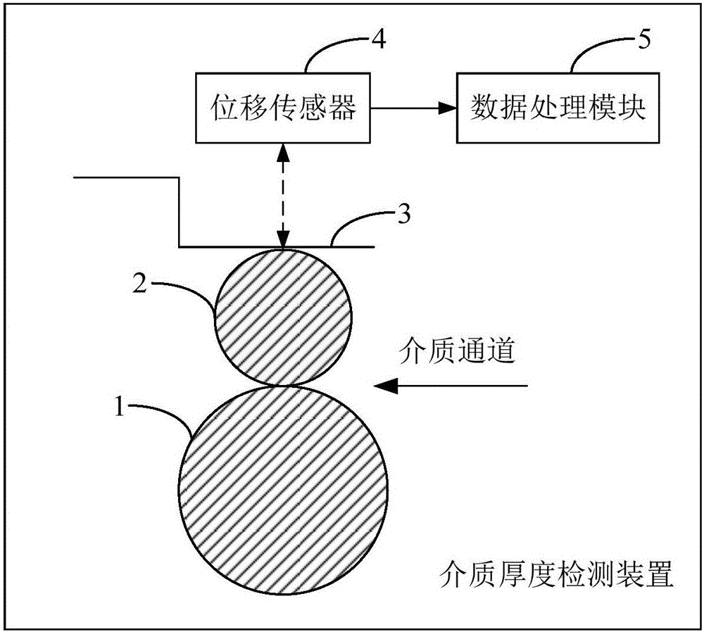
[0019] figure 2 The structure of the cross section of the medium thickness detection device provided by the first embodiment of the present invention is shown, and for the convenience of description, only the parts related to the embodiment of the present invention are shown.

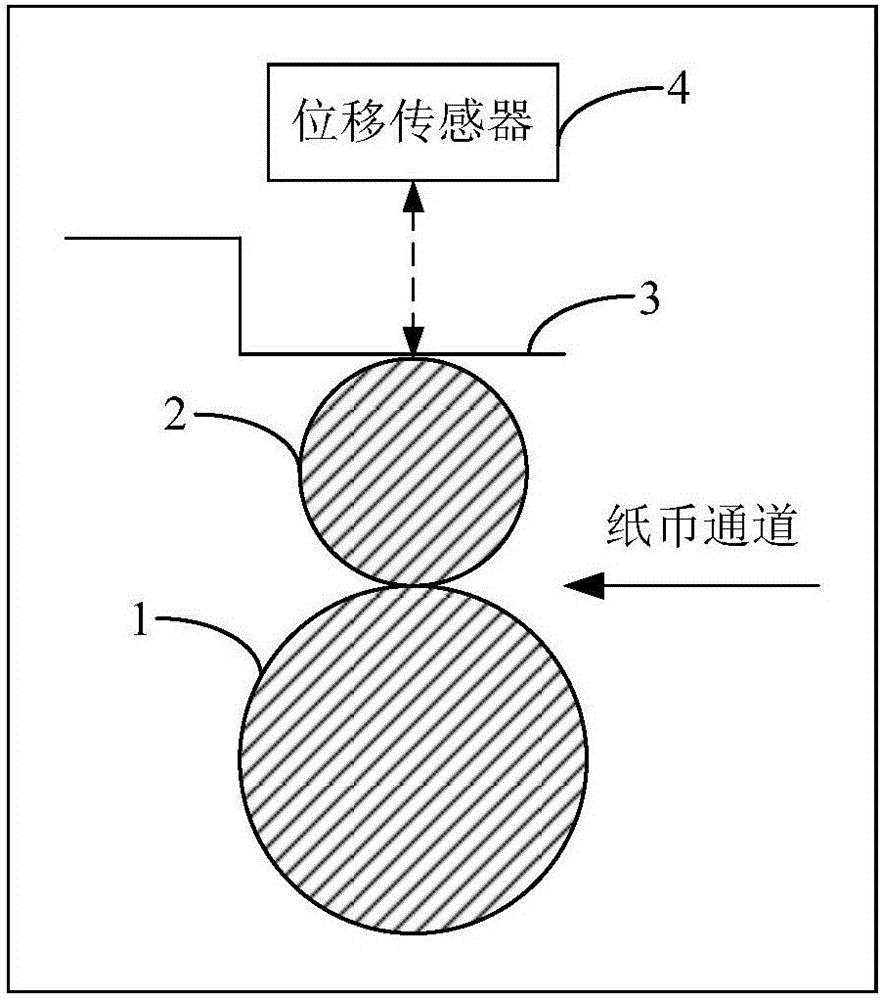
[0020] A medium thickness detection device connected to a motor (not shown in the figure), including a driving shaft 1, a floating shaft 2, a shrapnel 3 and a displacement sensor 4, the driving shaft 1 and the displacement sensor 4 are relatively fixed, and the floating shaft 2 and the shrapnel 3 are sequentially arranged between the driving shaft 1 and the displacement sensor 4, the floating shaft 2 is in contact with...

Embodiment 2

[0032] The second embodiment of the present invention provides a medium thickness detection method based on the medium thickness detection device provided in the first embodiment above.

[0033] image 3 A flow chart of the method for detecting the thickness of a medium provided by the second embodiment of the present invention is shown, and for the convenience of description, only the parts related to the embodiment of the present invention are shown.

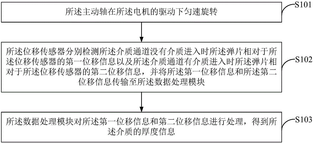
[0034] Such as image 3 As shown, a medium thickness detection method, comprising:

[0035] In step S101, the drive shaft rotates at a constant speed driven by the motor.

[0036] In step S102, the displacement sensor respectively detects the first displacement information of the shrapnel relative to the displacement sensor when there is no medium entering the medium channel and the second displacement information of the shrapnel relative to the displacement sensor when the medium channel has medium entering, and combines th...


PUM


Abstract

The invention belongs to the field of financial automatic equipment, and provides a medium thickness detection device and method. The medium thickness detection device comprising a driving shaft, a floating shaft, an elastic sheet, a displacement sensor and a data processing module is used, first displacement information of the elastic sheet relative to the displacement sensor when there is no medium entering a medium channel between the driving shaft and the floating shaft and second displacement information of the elastic sheet relative to the displacement sensor when there is a medium entering the medium channel are respectively detected through the displacement sensor, and the first displacement information and the second displacement information are processed through the data processing module so that actual thickness information of the medium is obtained, the influence of the processing error of the driving shaft on the detection result of the medium thickness information can be eliminated, the detection precision of the medium thickness detection device can be enhanced, the requirement for the processing precision of the driving shaft can also be reduced and thus processing cost can be reduced.

Description

technical field [0001] The invention belongs to the field of financial automatic equipment, and in particular relates to a medium thickness detection device and method. Background technique [0002] Existing financial automatic equipment, such as ATM deposit and withdrawal machines, are generally equipped with banknote thickness detection devices for detecting the thickness of banknotes, such as figure 1 As shown, the traditional banknote thickness detection device includes a driving shaft 1, a floating shaft 2, a shrapnel 3 and a displacement sensor 4, the driving shaft 1 and the displacement sensor 4 are relatively fixed, and the floating shaft 2 and the shrapnel 3 are sequentially arranged between the driving shaft 1 and the displacement sensor. Between the sensors 4, the floating shaft 2 is in contact with the driving shaft 1, and the contact between the floating shaft 1 and the driving shaft 2 is a banknote channel, the elastic piece 3 is fixedly connected with the axis...

Claims


Application Information

Patent Timeline
IPC IPC(8): G07D7/164
CPCG07D7/164
Inventor 陈胜斌
Owner SHENZHEN YIHUA COMP
Why Eureka
Try Eureka