
Micro-rail vehicle and suspension device thereof

A suspension device and vehicle technology, applied in the field of micro-rail transportation, can solve the problems of small space size, poor vibration damping effect, and inability to use a suspension vibration damping mechanism.

Active Publication Date: 2020-09-25
CRRC TANGSHAN CO LTD
View PDF5 Cites 0 Cited by
  • Summary
  • Abstract
  • Description
  • Claims
  • Application Information

AI Technical Summary

Problems solved by technology

Due to the small space size of the micro-rail vehicle, it is not possible to use the complex suspension damping mechanism of the suspended monorail vehicle
[0003] The structure of the suspension device of the existing micro-rail vehicle is simple, the boom and the carriage are directly connected by bolts, and the relative swing between the carriage and the running part is realized by the pin shaft, so the existing micro-rail vehicle cannot effectively block the vibration generated by the running part The problem of transmission to the carriage makes the existing micro-rail vehicles have poor vibration damping effect and cannot effectively limit the free swing of the vehicle

Method used


Image

  • Micro-rail vehicle and suspension device thereof
  • Micro-rail vehicle and suspension device thereof
  • Micro-rail vehicle and suspension device thereof

Examples


Embodiment 1

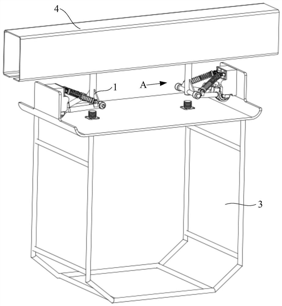
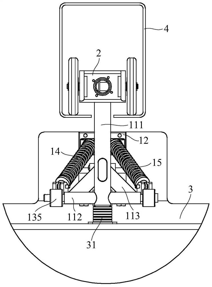
[0044] The present embodiment provides a kind of suspension device 1 that is used for micro-rail vehicle, and the operation structure schematic diagram of micro-rail vehicle can refer to figure 1 , figure 2 with Figure 4 , the suspension device 1 is hoisted on the running part 2 in the track 4, the carriage 3 is suspended on the running part 2 through the suspension device 1, and forms an integral structure with the running part 2; 2, the running part 2 moves along the track 4, a suspension device 1 is installed at the bottom of each running part 2, and the carriage 3 is hoisted on the track through the two running parts 2 and the matching suspension device 1 of the running part 2 4, so that the compartment 3 can move along the track 4 under the drive of the running part 2, so as to realize the purpose of transporting passengers;

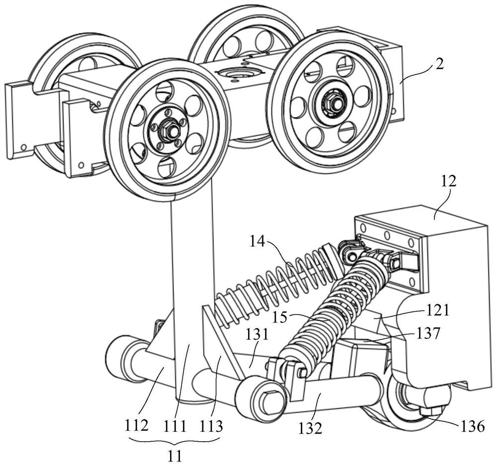
[0045] Please refer to image 3 with Figure 5 , the suspension device 1 includes a suspension 11, a mount 12, a V-shaped bar 13, a first ela...

Embodiment 2

[0052] This embodiment also provides a micro-track vehicle, such as figure 1 with Figure 4 As shown in the structure, the micro-rail vehicle includes a running part 2 and a carriage 3, and also includes any suspension device 1 provided in the above-mentioned embodiments. The suspension device 1 hangs the carriage 3 on the bottom of the running part 2. The running part 2 can be The track 4 moves; two suspension devices 1 oppositely arranged are connected between the running part 2 and the carriage 3, and the two suspension devices 1 are arranged along the traveling direction of the running part 2, and the two suspension devices 1 are installed on the top of the carriage 3 , and symmetrically arranged, so that the compartment 3 is suspended on the running part 2 from both ends of the traveling direction of the micro-rail vehicle;

[0053] Such as Figure 5 , Image 6 with Figure 7 As shown in the structure, an elastic stopper 31 corresponding to the bottom end surface of t...


PUM


Abstract

The invention relates to the technical field of micro-rail traffic, in particular to a micro-rail vehicle and a suspension device thereof. The suspension device comprises a suspension, a mounting base, a V-shaped rod, a first elastic piece and a second elastic piece; the top of the suspension is hoisted on a walking part; the mounting base is fixedly mounted at the top of the carriage; the V-shaped rod comprises a first supporting rod and a second supporting rod, the connecting ends of the first supporting rod and the second supporting rod are rotationally connected to the bottom of the mounting base, and the separating ends of the first supporting rod and the second supporting rod are rotationally connected to two sides of the bottom of the suspension; the first elastic piece and the second elastic piece are distributed in a splayed shape, the top end of the first elastic piece and the top end of the second elastic piece are hinged to the top of the mounting base, the bottom end of the first elastic piece is hinged to the first supporting rod, and the bottom end of the second elastic piece is hinged to the second supporting rod. According to the suspension device, the vibration reduction performance of the micro-rail vehicle can be enhanced, free swing of the carriage can be limited, and the riding comfort of passengers is improved.

Description

technical field [0001] The present application relates to the technical field of micro-rail transportation, in particular, to a micro-rail vehicle and a suspension device thereof. Background technique [0002] The suspension device of the existing micro-suspension vehicle needs to transmit the longitudinal force (traction force and braking force) of the running part to the suspension compartment, and at the same time bear the vertical force such as the gravity of the compartment, and ensure that the micro-suspension vehicle can be well Pass horizontal curves and ramps (vertical curves). Due to the small space size of the micro-rail vehicle, the complex suspension damping mechanism of the suspended monorail vehicle cannot be used. [0003] The structure of the suspension device of the existing micro-rail vehicle is simple, the boom and the carriage are directly connected by bolts, and the relative swing between the carriage and the running part is realized by the pin shaft, ...

Claims


Application Information

Patent Timeline
IPC IPC(8): B61B12/04
CPCB61B12/04
Inventor 耿庆厚李霞曹增招王艮川刘茜
Owner CRRC TANGSHAN CO LTD
Learn More