Power gear shifting transmission and vehicle

A power shift and transmission technology, applied in the field of power shift transmissions and vehicles, can solve the problems of large volume and high cost of power shift transmissions, achieve simple structure, reduce occupied space and production cost, and meet shifting requirements. Effect

Active Publication Date: 2020-09-25
柳工柳州传动件有限公司 +1
View PDF9 Cites 0 Cited by
  • Summary
  • Abstract
  • Description
  • Claims
  • Application Information

AI Technical Summary

Problems solved by technology

The power shift transmission adopting the above two structures has the defects of high cost and large volume, and is not suitable for mechanical equipment with limited installation space

Method used


Image

  • Power gear shifting transmission and vehicle
  • Power gear shifting transmission and vehicle

Examples


Embodiment 2

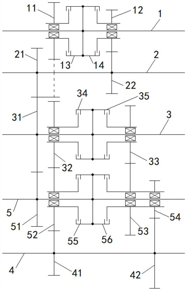
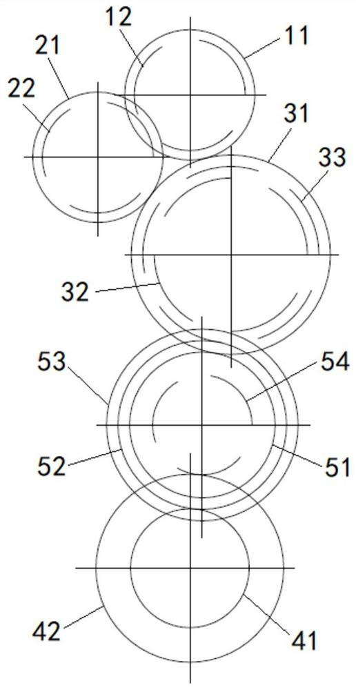
[0063] The difference between this embodiment and Embodiment 1 is that the number of teeth of the first fixed gear 21 is smaller than the number of teeth of the second fixed gear 22, and the first movable gear 11, the first fixed gear 21 and the third fixed gear 31 can be arranged on In the same plane, reduce the axial width of the transmission.

[0064] It should be noted that the first movable gear 11 and the first fixed gear 21 can also continue to be axially misaligned, but the axial width of the transmission will be correspondingly increased.

Embodiment 3

[0066] In this embodiment, on the basis of Embodiment 1, a fifth shaft parallel to the third shaft 4 is added, and the fifth shaft is provided with a seventh fixed gear fixed thereto; the seventh fixed gear and the fifth fixed gear 41 Or the sixth fixed gear 42 meshes.

[0067] In other embodiments, an eighth fixed gear fixed relative to the third shaft 4 and meshed with the seventh fixed gear can also be provided on the third shaft 4 .

[0068] In this embodiment, the fifth shaft is used as the output shaft, and the third shaft 4 is used as the shaft for power transmission between the input shaft 1 and the fifth shaft. Only one seventh fixed gear is arranged on the fifth shaft, and the The bearing force is relatively balanced. On the premise that the installation space meets the requirements, the power shift transmission provided by this embodiment can be used according to the requirements of the transmission ratio.

Embodiment 4

[0070]This embodiment provides a vehicle, including the power shift transmission defined in Embodiment 1 and an emergency shaft, wherein the third shaft 4 is parallel to the emergency shaft, and an emergency gear is arranged on the emergency shaft, and the emergency gear and the emergency gear are arranged on the third shaft. 4 and one of the gears that can be fixed relative to the third shaft 4 meshes, specifically, the emergency gear meshes with the fifth fixed gear 41 or the sixth fixed gear 42; the emergency gear is fixed relative to the emergency shaft, and the emergency shaft can selectively Connect or disconnect from the vehicle's steering system. As for how the emergency shaft is selectively connected or disconnected from the steering system, a clutch or other methods in the prior art can be used, which will not be described in detail here.

[0071] When the vehicle using the above-mentioned power shift transmission breaks down and cannot walk, it is usually dragged by...


PUM


Abstract

The invention relates to the field of transmissions and discloses a power gear shifting transmission and a vehicle. The power gear shifting transmission comprises an input shaft, a first shaft, a second shaft and a third shaft, wherein a first movable gear, a second movable gear, a first clutch and a second clutch are arranged on the first shaft, a first fixed gear and a second fixed gear are arranged on the second shaft, and a third fixed gear is arranged on the third shaft. According to the power gear shifting transmission, the third fixed gear meshes with the first movable gear while meshing with the first fixed gear, so that the rotation direction of the third shaft is changed during achievement of a forward gear and a reverse gear, the existing idle wheel design is cancelled, the number of shafts in the power gear shifting transmission is reduced, the size of the power gear shifting transmission is reduced, and the occupied space and the production cost of the power gear shiftingtransmission are reduced.

Description

technical field [0001] The invention relates to the field of transmissions, in particular to a power shift transmission and a vehicle. Background technique [0002] For a power shift transmission with many gears, such as four forward gears and four reverse gears, in order to meet the shifting requirements, there are mainly the following two methods, one is to use multiple gear shafts arranged in parallel , but the number of gear shafts is more; the other is to use fewer gear shafts, but more gears on each gear shaft. The power shift transmission adopting the above two structures has the disadvantages of high cost and large volume, and is not suitable for mechanical equipment with limited installation space. Contents of the invention [0003] The object of the present invention is to provide a power shift transmission and a vehicle, which can reduce the volume of the transmission and reduce the cost of the transmission. [0004] For reaching this purpose, the present inve...

Claims


Application Information

Patent Timeline
Patent Type & Authority Applications(China)
IPC IPC(8): F16H3/093F16H57/023
CPCF16H3/093F16H57/023F16H2057/02086F16H2057/02095Y02T10/62
Inventor 王松林杨浩蒋仁科鄢万斌曾垂远
Owner 柳工柳州传动件有限公司
Why Eureka
Try Eureka