
Selective vacuum resin hole plugging machine

A resin plug hole and selective technology, which is applied to the formation of electrical connection of printed components, electrical components, printed circuits, etc., can solve problems such as poor effect, and achieve the effects of convenient use, good foam breaking effect, and convenient use.

Inactive Publication Date: 2020-09-25
陈超鹏
View PDF1 Cites 0 Cited by
  • Summary
  • Abstract
  • Description
  • Claims
  • Application Information

AI Technical Summary

Problems solved by technology

However, the device is less effective in reducing the number of air bubbles by vacuuming

Method used

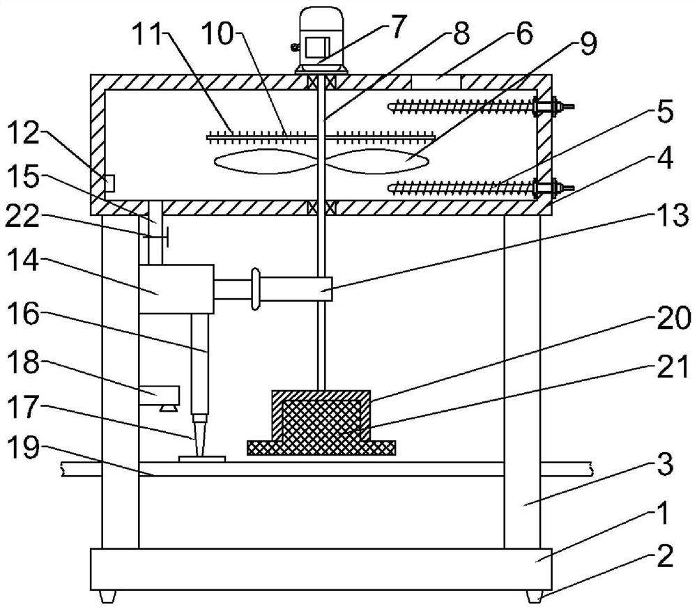
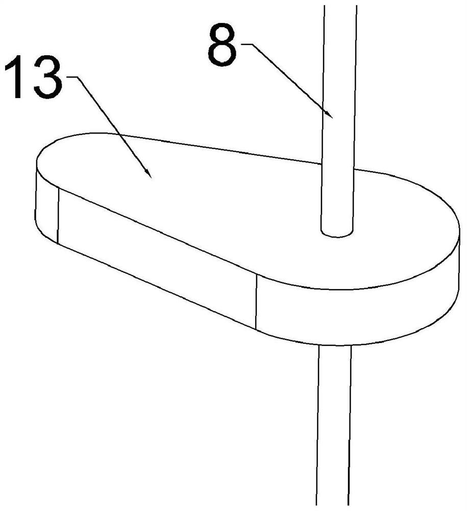
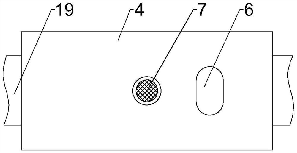

Image

  • Selective vacuum resin hole plugging machine
  • Selective vacuum resin hole plugging machine
  • Selective vacuum resin hole plugging machine

Examples


Embodiment 1

[0021] Example 1: Please refer to Figure 1-3 , a selective vacuum resin plugging machine, comprising a base 1, a support column 3 is fixedly connected symmetrically to the left and right above the base 1, a melting box 4 is fixedly connected to the top of the support column 3, and a plurality of electric heating tubes 5 are fixedly connected to the side wall of the melting box 4 , the top of the melting box 4 is fixedly connected with a motor 7, the output end of the motor 7 is fixedly connected with a longitudinal shaft 8, and the outer side of the longitudinal shaft 8 is fixedly connected with a stirring blade 9, and the stirring blade 9 is located in the melting box 4, above the stirring blade 9 A rotating breaking rod 10 is fixedly connected, and a plurality of defoaming needles 11 are fixedly connected to the outside of the rotating breaking rod 10, and a bubble detector 12 is fixedly connected to the left side of the bottom of the melting tank 4;

[0022] When in use, p...

Embodiment 2

[0030] Embodiment 2: This embodiment is a further improvement of the previous embodiment: the bottom of the longitudinal shaft 8 is fixedly connected with a connecting seat 20, and the bottom of the connecting seat 20 is fixedly connected with a sponge 21. The sponge 21 is located above the conveyor belt 19 and is completed in the plug hole. The workpiece that has plugged the hole in the back moves to the right along the conveyor belt 19, and contacts with the sponge 21, which will absorb excess resin to avoid excessive resin filling.

[0031] The working principle of the present invention is: when the present invention is in use, the resin material required for the plug hole is placed in the melting box 4, and then the electric heating tube 5 and the motor 7 are turned on and the solenoid valve 22 is closed, and the electric heating tube 5 heats the resin to melt it At the same time, the motor 7 rotates to drive the vertical shaft 8 to rotate, and the rotation of the vertical ...


PUM


Abstract

The invention discloses a selective vacuum resin hole plugging machine, and relates to a hole plugging machine. The machine comprises a base, supporting stand columns are fixedly connected above the base in a bilateral symmetry mode. The tops of the supporting columns are fixedly connected with melting boxes. A plurality of electric heating tubes are fixedly connected to the side wall of the melting box. A motor is fixedly connected to the top of the melting box, a longitudinal rotating shaft is fixedly connected to the output end of the motor, stirring blades are fixedly connected to the outer side of the longitudinal rotating shaft and located in the melting box, a rotating crushing rod is fixedly connected to the upper portions of the stirring blades, and a plurality of defoaming needles are fixedly connected to the outer side of the rotating crushing rod. The machine is simple in structure, the device is simple in structure and convenient to use, resin stirring and extrusion pump driving are achieved through the single motor in the using process, bubbles in resin are eliminated through the defoaming needle in the using process of the device, the bubble breaking effect is good,and bubble-free selective hole plugging is achieved in cooperation with the camera. In addition, excessive resin can be removed through the device, and the machine is more convenient to use and worthyof popularization.

Description

technical field [0001] The invention relates to a plugging machine, in particular to a selective vacuum resin plugging machine. Background technique [0002] The technological process of resin plugging has been widely used in the PCB industry in recent years, especially in some products with high layers and thick boards. It is hoped that the use of resin plug holes will solve a series of problems that cannot be solved by using green oil plug holes or press-fit resin. However, due to the characteristics of the resin used in this process, many difficulties need to be overcome in the production to obtain good quality of the resin plugged product. [0003] Chinese patent (authorized announcement number: CN204217235U) discloses a vacuum resin plugging machine, which includes a frame, a resin extrusion device, and a vacuum pump. The frame is provided with a vacuum chamber, and the resin extrusion device is arranged in the vacuum chamber. The extrusion device includes a resin ext...

Claims


Application Information

Patent Timeline
Patent Type & Authority Applications(China)
IPC IPC(8): H05K3/00H05K3/40
CPCH05K3/0094H05K3/40H05K2201/0959
Inventor 陈超鹏
Owner 陈超鹏
Learn More