

Dust detector of projection lens and dust remover
A projection lens and dust detection technology, applied in the field of data processing, can solve problems such as differences in judgment standards, heavy detection workload, and impact on dust detection effects, achieving high accuracy and improving efficiency
- Summary
- Abstract
- Description
- Claims
- Application Information
AI Technical Summary
Problems solved by technology
Method used
Image

Examples
Embodiment Construction
[0019] The specific implementations of the dust detection device and the dust removal device for the projection lens provided by the present invention will be described in detail below with reference to the accompanying drawings.
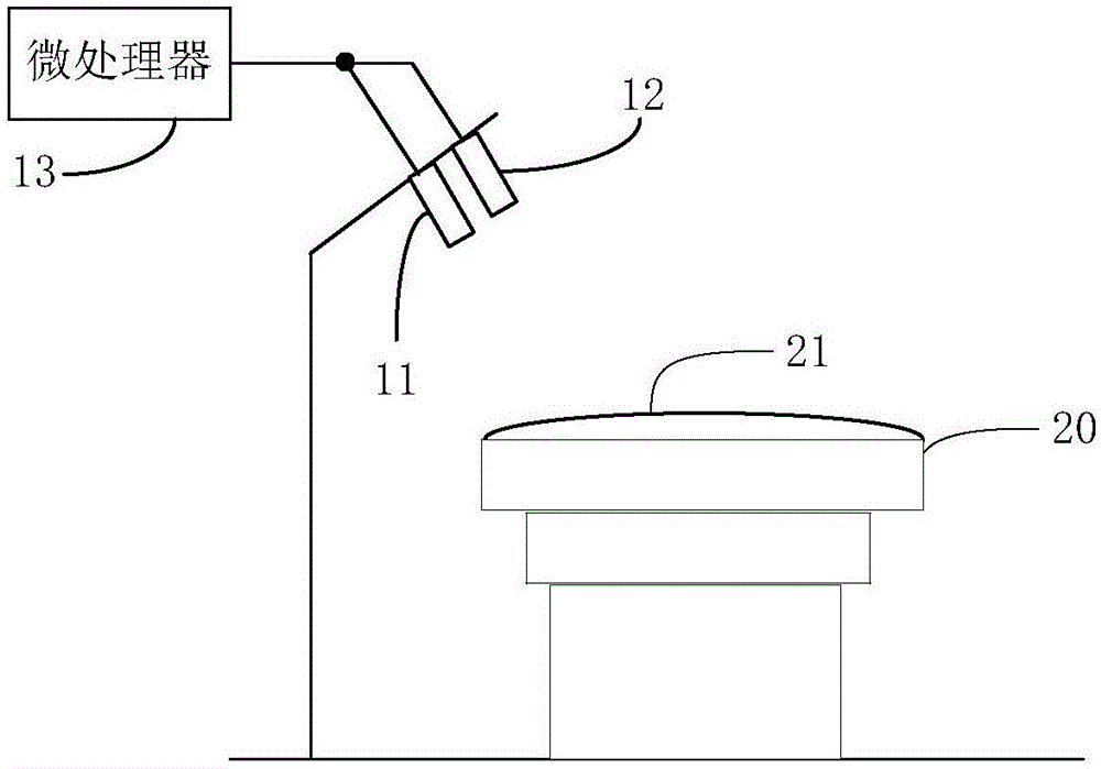
[0020] refer to figure 2 , figure 2 Shown is a schematic structural diagram of a dust detection device for a projection lens in an embodiment, including: a light emitting assembly 11, a light intensity detector 12 and a microprocessor 13;
[0021] The light-emitting assembly 11 and the light intensity detector 12 are respectively arranged on one side of the projection lens 20 through a bracket, and the microprocessor 13 is respectively connected to the light-emitting assembly 11 and the light intensity detector 12;
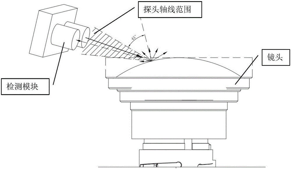
[0022] The light-emitting component 11 emits light to the lens 21 of the projection lens 20, and the light intensity detector 12 detects the light intensity of the light reflected by the lens after the lens 21 receives the light emit...
PUM
 Abstract
Description
Claims
Application Information